More processors in the chemical industry and elsewhere are opting to use rotary lobe pumps in applications formerly served by progressive cavity, diaphragm, peristaltic, screw and gear pumps. This trend is not surprising because lobe pumps offer benefits like low shear, reversible direction of flow, run-dry capability and easy cleaning between batches. Additionally, they have a proven track record in the food industry, where such pumps and their first cousins, circumferential piston pumps, have been widely used for half a century.
However, as with any pump, appropriate application requires knowledge of the advantages and disadvantages of the design. So, let’s examine factors to consider in selecting lobe pumps.
The basics
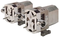
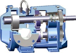
A lobe pump has two counter-rotating pumping elements (rotors), each with two or more lobes (Figure 1). Accordingly, there are two rotating shafts and two shaft seals. The drive shaft (connected to the driver) counter-rotates the driven shaft by means of oil- or grease-lubricated timing gears located outside of the pumping chamber.
Unlike a gear pump, the lobes never actually touch. This allows the rotors to be made of highly corrosion resistant materials like stainless steel and enables the pumping of non-lubricating liquids.
As the lobes separate on the suction side to create a void, fluid flows into the pumping chamber and is carried around the perimeter by each lobe’s fluid cavity. When the lobes re-converge, the cavity shrinks and the fluid is forced out the discharge port.
The rotors in lobe pumps take many forms (Figure 2), from two to six rounded lobes or two to three wings (sharp-edged, scimitar-shaped lobes). Each offers benefits and tradeoffs with respect to pump efficiency, solids handling, maintenance and fluid pulsation.
As in any positive displacement (PD) pump, efficiency is largely affected by slip, which is the backflow of liquid past the rotors from the high pressure (discharge) side to the low pressure (suction side) of the pump. Excessive slip results in reduced efficiency and limits the pressure that the pump can develop. The outer edges of the lobes, using very close clearances to minimize slip, provide a dynamic seal as they rotate within the pumping chamber. When pumping high viscosity liquids, the slip is negligible regardless of the lobe form used. Bi-wing (scimitar) lobes have slightly larger sealing surfaces, so they are often recommended for low viscosity liquids to minimize slip.
Rotary lobe pumps can handle liquids containing most solids found in chemical processing applications. For many solids, bi-wing rotors are selected because their leading edges tend to scoop solids into the cavity, unlike multi-lobe designs that may trap solids at the lobe tip. Bi-wing fluid cavities also are slightly larger than tri-lobe or multi-lobe designs, allowing slightly larger solids to pass.
Lobe pumps must be precisely adjusted to prevent rotor contact. This is typically accomplished by shimming at the timing gears. Bi-wing rotor pumps, though, generally do not require such shimming, which simplifies maintenance and frequently leads to their selection unless process reasons dictate otherwise.
If pulsation must be minimized in a process, however, then multi-lobe rotors are preferred. All PD pumps, even rotary pumps, by nature exhibit some pulsation in their flow. Multi-lobe rotors display higher frequency of pulsation but reduced amplitude compared to bi-wing rotors. Pulsation is proportional to operating pressure. So for those applications requiring near-zero pulsation, select a pump with multi-lobe rotors and operate it at the lowest discharge pressure possible. Where higher pressures are necessary, a pulsation dampener may be warranted on critical applications.
Shaft support
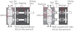
Pressure capabilities depend upon the type of shaft support provided. An overhung load design is typical of sanitary pumps (Figure 3, left). To eliminate areas where material could be trapped and bacteria could grow, there are no bushings (sleeve bearings) in the liquid. The seals are located between the lobes and the nearest shaft support. This design is limited to about 200 psi (14 bar) due to the potential for shaft deflection and rotor contact, but also is the fastest to clean in place by flushing or steaming. Many sanitary pumps have front-loading seals that provide easy access for maintenance.
A typical industrial design features bushing-type shaft support on both sides of the lobes (Figure 3, right). It allows pressures to 400 psi (27 bar) or more by minimizing shaft deflection. An air gap between the pumping chamber and the gearbox helps to prevent cross-contamination between the liquid pumped and the gear lubricant in the event of a seal failure. Shaft slingers or labyrinth seals are usually offered on the gearbox to provide additional protection against water or chemical infiltration.
Shaft sealing
Lobe pumps are not available in seal-less designs. All require two shaft seals; some types with bearings external to the liquid need four. Industrial lobe pumps offer at least as many sealing solutions as other rotary or centrifugal pumps —including packed glands, cartridge-style single or double mechanical or triple lip seals (Figure 4), and component-type single or double mechanical seals (Figure 5). API seal plans are available. So, if a specific brand or type of seal works well in your problem applications, it often can be applied to an industrial lobe pump. For sanitary lobe pumps in industrial applications, seal options include packing, O-ring seals, lip seals and component-type single and double mechanical seals, but standard cartridge seals are not an option.
Making a choice
The pump selection process involves too many variables to comprehensively discuss here. However, it is possible to give some general guidelines both for the initial step of choosing between PD and kinetic pumping principles, and then, if PD is picked, for selecting among lobe and other PD designs.
PD versus kinetic. Select PD over kinetic (used by centrifugal pumps) if:
• liquid viscosity exceeds 100 cSt (at which point centrifugal efficiency drops considerably);
• metering liquid into a process;
• reversible direction of flow is required;
• multiple viscosities may be handled by the same pump;
• suction lift may be necessary (such as with top-of-tank mounting); or
• liquid is shear sensitive.
Consider PD pumps, to achieve higher energy efficiency and lower cost of operation, for situations in which centrifugals are least efficient:
• moderately viscous liquids (from 25 cSt to 100 cSt);
• flow rates less than 50 gpm; or
• considerable potential variation in required flow rates (centrifugal operation very far from either side of the best efficiency point results in high cost of operation and can cause excessive wear, depending upon pump design).
Lobe vs. other PD options. If a PD pump is favored, consider lobe pumps when the application involves one or more of the following:
• shear sensitive materials;
• slightly to very viscous materials;
• solids present in the liquid;
• medium pressure (to 400 psi);
• steam cleaning or solvent flushing between batches;
• repeatable metering;
• reversal of flow direction; or
• the possibility of dry running.
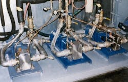
The primary liquid-characteristic drivers in selecting lobe pumps are shear sensitivity (dilatant or thixotropic fluids), entrained solids or non-lubricating liquids. The primary process-design drivers favoring lobe pumps are the need for frequent cleaning (especially between batches), metering high volumes into a process, or where the pump flow must be reversed to strip the discharge line (Figure 6). Some lobe pumps are designed to be mounted with ports in either a horizontal or vertical orientation and, when mounted vertically, can be self-draining to minimize loss of costly liquids and further shorten the cleaning cycle.
Operator preference often is a key factor in selection. Many operators simply prefer all metal pumps (lobe, gear or screw) over pumps with elastomeric members (progressive cavity, diaphragm or peristaltic), because rubber parts potentially wear, shed particles and require replacement.
How PD pumps compare
|
Decision Criteria |
Lobe |
Progressive Cavity |
Air-Operated Diaphragm |
Timed Two-Screw |
Gear |
|
Low shear (speed dependent) |
Excellent |
Excellent |
Excellent |
Excellent |
Excellent |
|
Efficiency |
Excellent |
Excellent |
Poor |
Excellent |
Excellent |
|
Reversible direction of flow |
Yes |
Model dependent |
No |
Model dependent |
Yes |
|
Run dry capability |
Excellent |
Poor |
Excellent |
Excellent |
Good (material dependent) |
|
Handling of thin to thick liquids |
Excellent |
Excellent |
Very good |
Excellent |
Excellent |
|
Cleanability |
Excellent |
Very good |
Good |
Good |
Good |
|
Pressure capabilities |
To 400 psi |
To >1,000 psi (multistages for higher pressure) |
Limited to plant air pressure, usually 100 psi |
To [greater than symbol]>1000 psi
|
Internal gear to 280 psi External gear to >1,000 psi |
|
Abrasive liquid handling |
Good |
Very good |
Very good |
Good |
Very good |
|
Metering capability |
Excellent |
Excellent |
Poor |
Excellent |
Excellent |
The table compares several types of PD pumps by some usual selection criteria. These comparisons are based on common types of pumps, and some models by specific manufacturers may vary from these generalizations.
Initial costs for lobe pumps can be higher than for some other PD units, because lobe pumps must include timing gears and typically do not operate at motor speeds (except for smaller sizes) and thus require either a gear reducer, gear motor, or belt- or variable-speed drive. Their high efficiency and low maintenance offset the initial costs, however, to achieve very reasonable life-cycle costs.
Lobe pump capacities range from 0.01 to more than 1,000 gpm (0.02 to >227 m3/hr). Units can handle viscosities from 28 to 2,000,000 SSU (1 to 440,000 cSt) and frequently deal with temperatures up to 400°F (204°C). Jackets can be provided for heating or cooling. Material options range from Alloy C to Type 316 stainless steel to cast iron. Because they are PD pumps, lobe units require some form of pressure relief, either integral to the pump or mounted on the discharge line.
Problem solvers
Lobe pumps frequently offer solutions for process applications that have caused plant engineers and operators headaches. Before selecting a lobe pump, however, users should understand how the pumps compare to kinetic and other PD technologies, and their benefits and tradeoffs. Additionally, to ensure getting the sought-after performance, users need to be aware of the variety of lobe pump designs available, particularly in the areas of lobe forms, shaft support and shaft sealing.
John Hall is product manager for Viking Pump, Inc., Cedar Falls, Iowa. E-mail him at [email protected].
|
Examples of materials and processes for which lobe pumps commonly are chosen include: Shear sensitive materials Other materials Processes |
