Energy savings are often disguised as problems
For those willing to look, and use some good old common sense, it is a land of opportunity. Just how expensive is compressed air? It takes about 8 hp of electrical energy to produce 1-hp-worth of work with compressed air. Using compressed air to cool electrical cabinets — a typical application — makes no sense! Here’s some food for thought:
- 1 cubic ft. per minute (cfm) cost - $100 per year in energy cost;
- 2 psig cost — $398 per year in energy cost for every 100-hp;
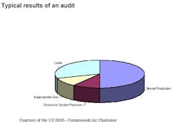
- 50% of the compressed air generated isn’t used for production (Figure 1).
Figure 1. It is not unusual for 50% of the air to be wasted in plant compressed-air systems.
The values are based on some assumptions: a compressor operates 8,000 hours a year; the cost of electricity is $0.06/kWh and the compressor produces 4.0 cfm at an expenditure of 1 hp (break horsepower) at a discharge temperature of 100°F and 100 psig. Considering the recent rise in energy costs an audit of the compressed air system could yield significant savings. Based on years of plant surveys, we expect that a Level One audit will identify a number of problems with air systems (Level 1: equipment supplying air: compressors, dryers, header, etc.; Level 2: equipment using air.). Here is what we typically see:
- Ignoring the electrical cost of compressors;
- Pressure losses;
- Air leaks;
- Running the header pressure higher than required;
- Pressure regulators operate full open (because they work better that way!);
- Inappropriate uses for compressed air;
- Not recovering heat;
- Inadequate or poor maintenance;
- Not measuring air usage.
Ignoring the cost
There is more to a compressed air system than pipes and a compressor. There is the supply side of the system and the demand side. The supply side may consist of an inlet filter, compressor(s), an after-cooler, a dryer, a receiver, and header piping. Never mind the fixed costs! It takes skilled labor, and electricity. Chilled water may be required for the after-cooler and dryer. Just operating a 100-hp compressor 24/7, 47-weeks/year will cost about $43,000/year ($0.06/kWh, 90% motor efficiency) in electricity alone. The demand-side is every application where air is used. A solenoid valve that stays open most of the time could cost you as much as $9,000/year — this is a demand-side loss. Your system works best when the flow and pressure produced by the supply side match the optimum conditions, i.e., minimum flow at lowest pressure, required by the demand side. Without a complete audit, how will you know what your real costs are?
Pressure losses are costing you money
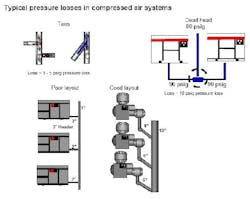
There are unnecessary losses on the supply side and on the demand side. Causes are: undersized equipment such as dryers and filters, undersized piping, dog-legs, crossing tees, and condensation (oil and water). In a well-designed system, the pressure drops in the piping before the dryer, and after, and to the header, should be zero; the velocity throughout the system should be less than 20 ft. per second (fps). The dryer and filter should have a drop less than 2 psig — together. If you don’t meet any of these conditions, then you are wasting power and disrupting the unloading controls on your compressors. This can be expensive: a reciprocating compressor can run at 0% power in the unloaded state; a screw compressor uses some power in this state. Some common pressure losses are shown in Figure 2.
Figure 2. A poor layout costs lots of money. (Click to enlarge.)
Compressed air leaks
After you have addressed problems with your layout, it is time to look at the next ranking problem: leaks. Thirty percent, or more, of lost air in most facilities is from leaks! It takes a cooperative effort to eliminate this cost. You need a leak management program involving maintenance and production. We suggest a plan with short- term and long-term objectives.
The goal of the short-term program is to determine which areas of the facility have the most leaks. Short-term means a year, with audits every three months. Inspections should be conducted with an ultrasonic leak locator when the plant is running and when it isn’t.
Goals for the long-term program are broader: educating personnel in operations and maintenance to identify and repair leaks. A material balance should be established for the plant and developed so air use for each department can be defined. Test the balance and update it. Providing incentives for conserving air can help drive down costs.
High header pressure
Every process in your plant that uses compressed air has a minimum pressure required to operate effectively. Except for the pressure drop in the delivery system, which should be minimized, extra pressure is a waste. Lower the pressure, save energy, right? Not when the perceived minimum pressure is high. The politically correct approach is to measure the equipment air flow and pressure required at the demand source. Once this is done, installing a receiver (a small vessel between the regulator and the process) or eliminating a restriction should help you find the real minimum.
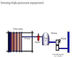
What if a high pressure really is needed? You may want to supply the local high-pressure need with a secondary, smaller, “booster” rather than drive the whole system at a higher pressure. The filter press (Figure 3) required a 100-psig minimum while the rest of the chemical plant ran well on 90 psig.
Figure 3. Use a booster for high equipment such as this filter press instead of keeping the entire system at high pressure.
Pressure regulators operate full open
Often the process regulator is wide open at the header pressure because the “droop” wasn’t allowed for. The regulator may be correctly sized but the gulp of air required is more than the line can supply. If, during the delay, there isn’t enough volume to hold the demand pressure, then the pressure falls. Production is negatively affected and the operator opens the regulator up to full line pressure. This is called “artificial demand.”
A fix for this problem is a receiver. This will hold the pressure until the regulator opens. One example is an air-driven agitator used for a settling pond. Three minutes of agitation at 150 cfm are required every 30 minutes to promote digestion. The pressure drop, measured for the cycle, is from 90 psig to 40 psig. The total air, based on the inlet pressure, required for agitation is 450 ft3 (3 minutes × 150 cfm). Therefore, the volume of the receiver should be at least:
VR = (450) (14.7)/ (40) = 165 ft3
Inappropriate uses for compressed air
This can be the most difficult problem to solve. The previous example could represent an inappropriate use of compressed air if electrical power is available. Some other applications could be:
- cooling for electric cabinet;
- vacuum (eductors);
- blowing, or blasting;
- pumps (air-diaphragm);
- air hoists;
- air vibrators; and
- sparging (agitating with air);
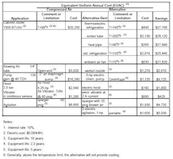
Table 1 summarizes typical savings possible by eliminating inappropriate uses of compressed air. Some applications, such as using an air eductor, or ejectors, to prime a suction-lift pump require compressed air only periodically. Still, it is worth noting that to produce 10 in. of Hg vacuum, at a flow of 10 cfm educted air (14.7 psia, 70°F), requires 8 cfm of compressed air (100 psig, 100°F). Often eductors are hard to replace with electric-driven vacuum pumps. Eductors can pump a corrosive fluid and pose lower risk in an intrinsically safe environment.
Table 1: Equivalent Uniform Annual Cost
For other applications, such as cooling electric cabinets, it’s easier to justify less-expensive alternatives. Cabinet cooling is often required to prolong the life of electronic equipment. Compressed air seems like a tempting choice. However, it’s apparent from Table 1 that it doesn’t make economic sense. There are several cost-efficient methods of cooling that are available, including vortex cooling, heat pipe, thermoelectric refrigeration, ambient air, and standard refrigeration.
In vortex cooling, compressed air is chilled by expansion and bled into a cabinet. Hot air in the cabinet is educted to the outside by the flow of the chilled compressed air. To economize on air and prevent condensation of moisture, vortex units should be equipped with an automatic temperature shutoff. Although the cost saving isn’t as significant as other alternatives, such as heat pipe and refrigeration, vortex cooling works up to 200°F.
The heat pipe is another substitute for compressed air. Cores of a heat pipe are made of a highly conductive material for cooling. As in a refrigerator, heat is transferred by changing the phase of a liquid. Heat is absorbed by the core, inside the cabinet, and passed to the fluid inside the pipe. The fluid is vaporized and flows outside of the cabinet where it is condensed. In the air-cooled version, an exterior fan draws heat away from the core, which cools the internal cabinet without exposing the interior to ambient air. The fluid is condensed and returned to the core inside the cabinet for another cycle. The air-cooled version is limited by the ambient temperature of the outside air. The heat pipe offers the best economic choice, where physical limits allow (Table 1).
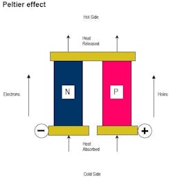
Thermoelectric refrigeration offers the greatest flexibility and has the second lowest annual cost. This type of refrigeration operates using the Peltier effect: when two dissimilar metals or semiconductors are connected together, current drives heat from one terminal to another. Refrigeration units consist of an array of p-type and n-type semiconductor elements connected (Figure 4).
Figure 4. Thermoelectric refrigeration works by forcing electrons to overcome resistance.
Heat is carried by electrons, in the n-type, and the holes created by electrons, in the p-type. The heat pumping capacity of a module is proportional to the current and is dependent on the element geometry, the number of couples, and the material properties. Current technology is limited; 1,500 BTU appears to be the largest available — now.
Other options for cabinet cooling have their own niche. Fan cooling and standard refrigeration can certainly compete for large cabinets. Fans are limited by ambient air temperature but are inexpensive. One unique place for fans is in coolers or other areas that are already cooled. Refrigeration may be the only choice for large cabinets in hot zones.
Blowing cash away
Another common waste of compressed air, apparent to anyone who has visited a packaging area, is the use of air to blow products or dust. A ¼-in. line will flow 32 cfm at 80 psig. An open-ended blow tube represents an annual loss of more than $3,800 (Table 1). Regardless of the application, several guidelines should be applied to compressed air being used for open blow-off: 1) use anything else whenever possible; 2) use low pressure air from a blower — the lower the pressure the lower the cost; 3) regulate the flow to the lowest effective pressure — know the pressure! 4) use a venturi nozzle or air inducer to reduce compressed air used; and 4) shut-off blow-off air (automatically) when not needed for production.
Air amplifiers, or inducers, will reduce compressed air flow, where a mechanical method, such as a wiper, cannot replace blow-off. Air amplifiers use “venturi” action to pull in ambient air and mix it directly into the compressed air stream. The ratio of ambient air drawn in can be substantial. Amplification ratios up to 25:1 are possible. Using 10 cfm of compressed air can produce up to 250 cfm of blow-off air. This is a savings of 15 cfm of compressed air per ¼-in. blow-off.
Although air-operated diaphragm pumps are not very energy efficient, they tolerate aggressive conditions well and are not seriously damaged if run dry. Also, they are not a serious hazard in intrinsically safe environments. If an electric pump — diaphragm, centrifugal or progressive cavity — can be made to work, it will usually be cost-effective. When an air-diaphragm pump is the still the best choice, reduce the utility costs by either shutting off the air if the pump is not needed, or lowering the supply pressure. Generally, when a pump must operate for long periods, an electric pump will save money over an air-diaphragm pump (Table 1).
Air hoists and air vibrators are sometimes chosen when electricity is not available or where the area is intrinsically safe. This safety issue is generally not a concern with pumps and agitators where isolation is easier. Hoists and vibrators pose other concerns. Air hoists used only occasionally have a high incidence of unnoticed air leaks. High pressure air is required by air vibrators to be effective; economically, they are often a poor choice — except where small size is needed.
Sparging with air may be necessary if the product is sensitive, e.g., friable, or where mixing mechanically is not economical or practical. One example where mechanical mixing might be uneconomical would be where a tank is very long, requiring an agitator with a long shaft. Another would be where air is available but electricity is not. If mixing by sparging is the best solution, doing so at the lowest possible pressure reduces the cost (Table 1). Use low-pressure air supplied by a blower, if available. Use a step-down regulator on compressed air, if only high-pressure air is available.
Not recovering heat
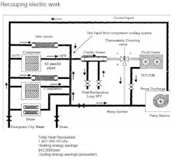
Compressing a gas generates a lot of heat. However, 85% to 90% of the motor horsepower used to run a rotary screw air compressor can be recovered in the form of heated air or water. Similar recovery, in the form of heated water, is possible with water-cooled compressors. It takes 8 hp of electrical energy to produce 1 hp of air power. That means that a portion of the 7 hp of unused energy is available as heat. Recouped heat can be used in many ways: 1) space heaters; 2) heating process water; 3) boiler make-up; 4) and running a “heat of compression” desiccant dryer. Figure 5 depicts a typical reclamation system.
Figure 5. Cooling needed for air compressors can be turned into heating savings.
Fix it when it breaks
This seems to be the modus operandi with utilities. Too often maintenance on compressed air is viewed as an expense when it is really an opportunity for savings. Maintenance on the supply side has a direct impact on plant energy use.
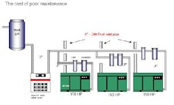
On a recent audit, we found a compressed air system sorely in need of basic maintenance (Figure 6). Dirty inlet filters lowered the inlet pressure from an expected 14.2 psia to 9.5 psia. This reduced the air production from each rotary screw compressor from 725 scfm to 501 scfm — a loss of 31%. All three compressors were run at full load to supply the 1,400 scfm demand. Correcting this problem saved $45,000/year in electricity.
Figure 6. Dirty inlet piping costs $45,000/year. (Click to enlarge.)
Audits also are useful in identifying residual design errors. Figure 6 shows two typical errors. First, a riser after the dryer could collect condensate, which can cause a drag on gas flow. Normally, dips in piping are allowable but should include a receiver and condensate trap; a riser at the dryer discharge is an exception. The second error is the use of tees instead of wyes. Another potential savings overlooked is using outside air (cold air is denser than heated air).
A high pressure drop in filters and separators is a problem we see a lot. If you knew what power costs per psig, then you would probably re-evaluate your schedule for changing separators and filters. A typical pressure drop for a new oil separator is 2-3 psig. After two years, the pressure drop may be 10-12 psig. With the cost of $200/year per 1 psig ($0.06/kWh), and assuming replacement elements cost $550/each, it is prudent to change the elements somewhere between 3-4 psig.
Measurement
If you don’t measure it, you can’t manage it! Do you have a material balance for compressed air? Are the minimum flow and minimum pressure documented for all of your equipment? Are you monitoring your compressor cycle times and power usage? Is anyone keeping track of tie-ins for new equipment or do you have a single 1-in. pipe feeding five packaging machines when a separate line should have been built for all five machines? Do you have flow meters installed at key points in your piping network — if so, when were they last calibrated? Most of the plants we have audited have flow meters on the main air supply but few in the production areas, with calibration every 10 years, whether they need it or not! As for pressure, we generally find that no test points or gages are installed in critical interconnecting pipes.
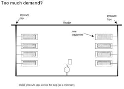
What can you do to initiate a plan for monitoring your compressed air? Install test points for pressure gauges at the compressor discharge, before the pre-filter and dryer, after the after-filter and throughout the demand side of the piping. This is especially true for loops where a series of equipment is supplied (Figure 7). Install flow meters at branches in the system. After you have installed flow meters, try to solve the material balance. Most of the time, you will find you missed something.
Figure 7. Install a loop to balance the load on the system.
Another common problem is gage accuracy. Although it may be useful to install gauges to monitor pressures at the demand points, don’t use these values in calculations! Unless instruments are periodically calibrated, and this goes for flow meters as well, they will drift. Because even calibrated gauges can differ in accuracy, measure differential pressures throughout the network with a single test gage. For our purposes, we rely on high quality digital gages. We use the same gauge, which has been calibrated prior to being employed. This is the only way to know what is going on.
Sometime during the discussion about a measurement plan someone will ask about measuring the dew point in the system. Technically, this is known as the pressure dew point (PDP). The damage that moisture causes to some equipment will be itemized as justification for a humidity meter. Generally, measuring the PDP is unnecessary. If you have a moisture problem eliminate it! Some industries, such as pharmaceuticals, food, cosmetics and fine chemicals (refer to ISO 8573.1) may have air quality standards that require permanent monitoring of humidity. These instruments are delicate and need annual calibration.
A well-managed system
How do you know when your air compressor system is performing at maximum efficiency?
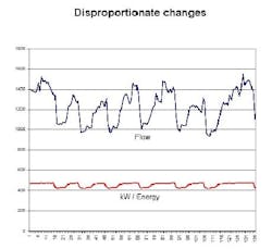
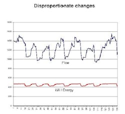
Figure 8. In a poorly managed system, power usage does not respond to change in demand.
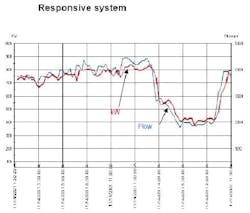
Figure 8 shows a stable well-managed system. A conservation program is in-place, air quality meets standards, and pressure drops have been eliminated on both the demand-side and supply-side. The trouble is that the cost savings are impressive but the power usage is still a little higher than expected — what’s wrong? Look at Figure 8. The chart shows that power doesn’t respond to demand, i.e., flow: reduced demand should mean less power — right? What is needed is an air management system to assure that all compressors run at full-load efficiency. This system must have software capable of analyzing operating condition, compressor load condition, and adjusting to pressure change — either rise or decay. The net result will be all units on at full demand (load), one on at partial load, and all other off, 80% to 85% of the time. Figure 9 shows the results of installing a management system.
Figure 9. In an optimized compressed air system, power responds to demand.
Another component of a well-managed system is keeping it in tune. This requires an annual check-up, and a monitoring system. Monitoring systems are available to do this on a continuous basis.
A final component is training. Operating and maintaining a compressed air system requires the efforts and talents of many people. To be effective, these people must understand how your system works and how interdependency of its components affects cost. It has been our experience that this type of training pays off quickly.
Energy savings go directly to the bottom line. Saving money in compressed air will not only reduce costs it will increase plant production.
