Gear pumps rely on two meshing gears to cause liquid flow. They are precision machines with extremely tight fits and tolerances, and are capable of working against high differential pressures. They come in two types: two gears with external teeth or one gear with external teeth within another with internal teeth.
The most common uses for gear pumps are to move chemical and petrochemical liquids that have relatively high viscosity; to supply fuel oil for burners or other facilities; and to transfer gasoline, kerosene, fuel oil and diesel oil. They also feature in hydraulic devices such as actuators, damper controls and elevators. In addition, they pump coolants, paints, bleaches, solvents, syrups, glues, greases, asphalt, petroleum and lubrication oils, and handle many general industrial applications.
Gear pumps, when properly designed and engineered, can offer many advantages. These include compactness, simplicity, easy serviceability, bidirectional and pulseless flow, self-priming, low net positive suction head requirement, high mean time between maintenance, high-pressure and high-temperature capability, precise and accurate metering, and availability in multiple seal configurations or with sealless magnetic drives.
The pumps can tolerate suspended small solids in abrasive applications but gradually will wear and lose performance.
Gear pumps are available in a variety of materials of construction, including cast iron, cast steel, stainless steel, high-nickel alloys and lightweight advanced aluminum alloys. They usually come in numerous optional designs, such as close-coupled, abrasion-resistant and API-standard compliant.
External Gear Pumps
In external gear pumps, a casing encloses two meshing gears with external teeth (Figure 1). A rotating shaft drives one gear, which then moves the other gear. The turning of the gears causes liquid to enter the inlet (suction) port, flow into and around the outer periphery of the gears, and then exit through the outlet (discharge) port. The size of the cavity (volume) between the teeth and the speed of the gears regulates this flow. The amount of liquid that slips back to the inlet port also affects the discharge flow. The degree of slip depends upon the side clearance of the gears to the casing, the peripheral clearance of the gear and bore in the casing, gear-to-gear clearance, developed pressure and the viscosity of the liquid — the lower the viscosity, the greater the slippage.
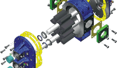
Figure 1. Both gears have external teeth. Source: NAPCO Pump.
Most external gear pumps use spur, helical or herringbone gears. The helical and herringbone gears deliver more flow and higher pressure. They are quieter than spur gears but may require more net inlet pressure.
As very rough indication for common applications, the rated performance range is 1–500 m3/h with discharge pressures of 3–90 Barg (higher pressures are possible) and power ratings of 0.3–300 kW. Small external gear pumps frequently operate at four-pole motor speeds (1,800 rpm) and have operated at two-pole speeds (3,600 rpm). As the pump capacity per revolution goes up, speed usually is reduced; it could be less than 500 rpm. Operating speeds and flow rates generally are decreased as the liquid viscosity increases.
Internal Gear Pumps
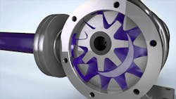
In internal gear pumps, a gear with internal teeth meshes with a gear with external teeth (Figure 2). These pumps may come with or without a crescent-shaped partition. Designs are available to provide the same direction of flow regardless of the direction of shaft rotation.
The gears demeshing on the inlet side draw liquid into the pump. The mechanical contacts between the gears form a part of the moving seal between the inlet and outlet ports. The meshing of the gears forces the liquid out the discharge port.
The pumps’ relatively low speed and inlet pressure requirements often make them more-efficient alternatives to centrifugal pumps, especially as liquid viscosity increases. These designs have proven reliable, simple to operate, and easy to maintain.
As a rough indication, commercially available internal gear pumps can provide flows from 1–400 m3/h and discharge pressures to 40 Barg (sometimes more). The pumps typically contain at least one bushing in the liquid. They can be damaged when pumping large solids.
Figure 2. A gear with external teeth is positioned within a gear with internal teeth. Source: Maag Industrial.
Pinion-drive internal gear pumps are a distinctive subclass with unique operating characteristics. They generally are direct-drive arrangements operating at two-, four- and six-pole speeds, usually used for clear to very light abrasion, low-viscosity liquids such as hydrocarbon-based ones. They come in single or multistage module designs capable of pressures to 200 Barg (sometimes more).
Viscosity Range
As already noted, gear pumps often are chosen to handle high viscosity liquids. The tight clearances of their working parts enable effective pumping of liquids against high pressure. Low viscosity liquids have more of a tendency to slip through these tight spaces from the higher-pressure discharge side of the pump back to the lower-pressure suction side of the pump. The phenomenon of slip causes a reduction in flow rate and pump efficiency. Slip depends upon the magnitude of the differential pressure (for example, the difference between the discharge and suction pressures), the viscosity of the liquid and the working clearances inside the pump. Slip goes up as viscosity decreases, and as differential pressure and gear-housing clearances increase; it usually is measured as a percent decrease from ideal flow (e.g., flow with zero slip). The “flow versus pressure” curves for thin liquids (those with relatively low viscosities) have high slopes, which indicate significant reductions in flow rate with increasing differential pressure.
Gear pumps generally suit liquids with kinematic viscosities in the range of about 2 to 400,000 cSt. As another very rough indication, gear pumps are used for liquids that have viscosity more than two times greater than that of water, which is about 1 cSt. Slippage often nears zero when kinematic viscosity approaches about 300–1,000 cSt. Higher viscosity liquids generally require lower pump speed to allow the liquid to fill the space between the rotating gear teeth.
A number of liquids with viscosities approximately 3–30 times that of water are relatively common in chemical processing; for instance, ethylene glycol has a viscosity around 16 times greater than water. Processors also use liquids with viscosities 100–1,200 times higher than water; a good example is glycerol, a simple polyol compound with a viscosity around 1,000 times that of water, which is used in some pharmaceutical operations. (Equipment lubricants such as motor and gear oils typically fall in that range, as do some heavy fuel oils.) Gear pumps can handle materials with viscosities in range of 3,000–10,000 times that of water that behave like honey and even those with viscosities in range of 50,000–200,000 times that of water that act akin to peanut butter.
Mechanical Features
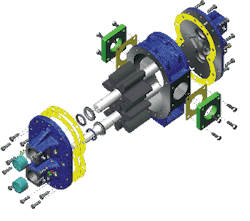
Gear pumps consist of two intermeshing, hardened-steel, precision-ground gear assemblies enclosed in a robust casing with high-strength front and back covers. One gear assembly contains the drive gear — connected to or installed on a precision-ground and polished drive shaft that usually extends outside the pump to permit coupling to an external prime mover such as an electric motor. The other assembly contains the driven gear, often known as the idler gear — connected to or installed on a precision-ground and polished driven shaft.
The drive gear turns the driven gear in the opposite direction to its rotation. The gears’ movement causes the liquid, which is trapped in the gear teeth spaces between the housing bore and the outside of the gears, to flow from the inlet side of the pump to the outlet side with virtually no pulsations. The pumped liquid travels around the gears, not between them.
Retaining rings, installed in grooves provided on the shaft, or other arrangements ensure the gears will not move axially. Most often, another system or component, such as a key, keeps the drive gear from moving radially. A seal system at the drive shaft, often lip-type shaft seals, prevents external leakage of liquid. If lip-type shaft seals are used, the sealing lip in contact with the liquid usually is spring-loaded. Vent passages within the housings and driven shaft communicate pump inlet pressure to the rotary seal area, thus imposing the lowest possible pressure at the rotary seal for extended seal life.
An important advantage of gear pumps is their self-priming capability. The rotating gears evacuate air in the suction line, producing a partial vacuum that allows the atmospheric pressure to force liquid into the inlet side of the pump. This makes a gear pump an ideal choice when the application requires the pump to be located above the liquid level. Because gear pumps can’t create a perfect vacuum, the total lift (including pipe friction losses) shouldn’t exceed one half of the atmospheric pressure.
However, the close tolerances and tight spaces inside gear pumps restrict the pumping of liquids containing abrasives. This is because the abrasive particles can cause accelerated wear that rapidly can reduce pump performance. The wear rate depends upon the hardness, size and concentration of the particles, and the operating speed of the pump. Pumping thin (relatively low viscosity) liquids also can adversely affect the wear rate because they have poor lubricating properties. So, take extra care when selecting materials for the components of gear pumps for such applications. Special materials (such as carbon graphite) are available to increase lubrication and resist wear when pumping extremely thin liquids or those containing abrasives.
With good design, manufacturing and assembly, practically no leakage occurs through the teeth because the driving contact forms an effective seal at (nearly) all points. Liquid leaks from pressure to suction around the circumference over the teeth, and across the flat end faces of the gears. The end leakage is partly radial and partly across the teeth in the neighborhood of the meshing point. Keeping the gear approximately in the center of its end clearance can control leakage.
The pressure head of gear pumps expends itself along the leakage paths partly in overcoming the viscous resistance and partly in providing the kinetic energy in the leakage stream. The viscosity of the liquid in the actual leakage paths isn’t necessarily the same as that of the liquid flowing into the pump; it may change particularly because of the heat generated by loss of power. Such power loss potentially could cause a considerable rise in temperature in high-pressure gear pumps, where both the flow and specific heat of the liquid are small in relation to the power loss.
A small increase in the end or diametrical clearance of the gears in their chambers will lead to a large drop in volumetric efficiency. Clean liquids usually cause very little wear. However, gear pumps are sensitive to foreign matter in the liquid on account of their light alloy casings. The foreign matter apt to create damage includes both dirt and scale from the upstream system and metal particles abraded from high spots of the pump itself, particularly in the early period of its life. Large particles gravitate to the periphery of the gear under the action of centrifugal force and score circumferential grooves in the casing while smaller particles could embed themselves in components such as the cages of bearings.
Thus, filtration of the liquid before it enters the pump often makes sense. Fine multistage filters usually work well; a so-called 100% filtration system typically includes three stages: a wire-mesh filter to take the whole flow, a cloth or felt filter to remove the finer particles from the flow, and a final polishing filter. Where for any reason you can’t avoid a certain amount of foreign matter in the liquid, don’t select light alloy casings and ensure both the gears and the cylindrical part of the casing are as hard as possible. However, the flat ends of the casing should be faced with softer material to minimize the risk of seizure. In such situations, consider employing lower speeds to minimize the centrifugal action on the foreign particles.


