Processing Equipment: Take Advantage of Liquid-Ring Compressors
Liquid-ring compressors possess a number of desirable features. They provide a fairly steady gas flow with very small pressure fluctuations, and have low noise levels and smooth running characteristics. Including ancillary equipment, they offer a favorable capacity-to-weight ratio and small footprint, which are important advantages for small compressor packages that should be lightweight and compact. Moreover, their full-load and part-load performance is reasonably good, often better than many other compressors. A back-pullout design enables maintenance of the compressors without disassembly of piping and service liquid connections.
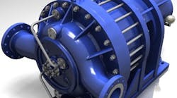
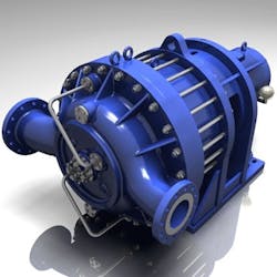
Figure 1. A unit such as this can handle a variety of small services. Source: Gardner Denver.
A liquid-ring compressor (Figure 1) is a rotating positive-displacement device that is very similar to a rotary vane compressor; it differs in having vanes that are an integral part of the rotor that churn a rotating ring of liquid to form the compression chamber seal. Both types of compressors are inherently low-friction designs, with the rotor being the only moving part. Sliding friction often is limited to the shaft seals, although other frictions might exist. Many points presented in this article actually apply to both types.
An induction motor typically powers a liquid-ring compressor. The motor rotates a vaned impeller located within a cylindrical casing to compress gas. Liquid (often water) is fed into the compressor and, by centrifugal acceleration, forms a moving cylindrical ring against the inside wall of the casing. This liquid ring creates a series of seals in the space between the impeller vanes, forming compression chambers. The eccentricity between the impeller’s axis of rotation and the casing geometric axis results in a cyclic variation of the volume enclosed by the vanes and the ring. Gas is drawn into the compressor via an inlet port in the end of the casing; the gas is trapped in the compression chambers created by the impeller vanes and the liquid ring. The reduction in volume of the gas caused by the impeller rotation compresses the gas, which exits through the discharge port in the end of the casing.
[callToAction]
Liquid-ring compressors come in single- and multi-stage versions. A multi-stage compressor typically has up to two compression stages (in rare cases, three) on a common shaft. At process plants, such units handle many small vacuum and compression services, e.g., in distillation, and vapor and flare-gas recovery.
Broad Applicability
Water commonly serves as sealant for liquid-ring compressors, with oil the second most-popular choice. However, the devices can use any fluid compatible with the process (provided it has the appropriate vapor-pressure properties) as the sealant liquid. This ability to use any liquid makes the liquid-ring compressor an ideal choice for solvent (vapor) recoveries and similar services. If an operation such as vacuum, drying, etc. is generating vapors of difficult-to-handle compounds (such as toluene), then it’s possible to use the same material in the liquid form (liquid toluene in this example) as the sealant, provided the cooling system (usually cooling water) can keep the vapor pressure of the sealant liquid low enough to pull the desired vacuum to suck and compress the vapor.
In vacuum services, the vapor pressure of the ring liquid usually limits the attainable pressure reduction. As the generated vacuum approaches the vapor pressure of the ring liquid, the increasing volume of vapor released from the ring liquid diminishes the remaining vacuum capacity. The efficiency of the system could decline as a result. As a general rule, single-stage vacuum compressors typically produce vacuum to 0.06 bar and two-stage units can produce vacuum to 0.03 bar (or sometimes lower), assuming air is being pumped and the ring liquid is water at a temperature of 15°C or less. Most manufactures use dry air and 15°C sealant-water temperature as the basis for their standard performance curves.
For compression, single-stage liquid-ring compressors usually are used. As a rough guide, their maximum discharge pressure most often is less than 6 barg, while two-stage versions can provide discharge pressures up to around 16 barg.
Design And Operation
Liquid-ring compressors employ a rotor centrally positioned in an oval-shaped casing. The rotor does not touch the casing, which contains a precise amount of liquid. During rotation, centrifugal force causes the liquid to form a ring that follows the shape of the casing’s inside wall. Because of that oval shape, the volumes between the rotor’s blades differ. At two points, the liquid completely fills the volumes. In between these two points, the liquid recedes in the beginning and up to half way, thus creating suction; it then advances, creating pressure. The gas enters the casing through the inlet port, where suction is generated, and leaves, after compression, through the outlet port. A dedicated line supplies the sealant liquid, which flows continuously. This liquid absorbs the heat of compression. It usually leaves the casing together with the compressed gas, and is split off in a discharge separator tank.
The operation of rotary vane compressor is slightly different: the centrifugal force acting on the blades due to rotor rotation pushes the blades radially outward to continuously contact the cylinder bore and form closed pockets or cells filled with gas when open to the inlet port during the (nearly) half of revolution on the inlet side of the cylinder. During the second half of revolution, a cell moves toward the discharge port while its volume decreases due to the progressively diminishing space between the cylinder and rotor. Thus, a blade is subjected to a pressure differential between its preceding cell at a higher pressure and the following cell at a lower pressure. This pressure differential can cause the blade to rub against the outer corner of the rotor slot as it slides in and out of the slot.
Cylindrical gas distributors and relatively large inlet-gas passages can reduce friction losses to the minimum. An overhung arrangement often is preferred for these small compressors because it requires only one shaft seal and bearing housings are externally accessible.
Liquid-ring compressors usually come fitted with rolling-element bearings. Unfortunately, the compressor’s small size often rules out more-reliable bearings such as hydrodynamic ones. So, it’s essential to select rolling-elements bearings that promise reasonable reliability and performance. As a very rough guide, choose rolling elements that have an 8-y theoretical operating life or more; a basic life (L10) exceeding 60,000 hours or more is preferred. The bearing life calculation should consider all possible loads — for instance, all potential dynamic loads, high loads due to compressor degradation and fouling, and all other non-ideal cases. Review of many failed rolling-element bearings has shown they were subjected to actual loads much greater than the theoretical (assumed) ones; such higher actual loads can reduce the bearing life to 5–10% or less of the expected life.
Lubrication
Lubrication requirements vary. In some liquid-ring compressors, the oil is re-circulated, in others it leaves the compressor with the discharge gas, and in some others it serves a dual purpose of lubrication and cooling. A force-feed lubricator with adjustable capacity usually pumps the lubrication oil through tubing lines to several drilled openings in the side of cylinder and to each bearing.
Often lubrication oil is expected to protect bearings and sliding surfaces and to remove heat. The lubrication oil also assists the smooth operation of sliding motions of compressor components and reduces wear between different components.
The lubrication oil encounters temperatures that are much lower than those in other positive-displacement compressors such as the corresponding reciprocating ones. The lubrication oil rarely faces temperatures over 100°C; the temperature typically is 90°C or less.
Elevated temperatures because of suction-gas high temperatures or compressor malfunction can adversely affect petroleum oils (mineral oils), causing them to break down to form carbon and varnish deposits. The liquids or condensates often change the oil’s properties and may react with some of its additives. In the case of a hydrocarbon gas compressor (such as one for natural gas or flare-gas recovery), some heavy hydrocarbons may condense into liquids in so-called cold places (such as close to the cooling-water jackets) and dilute the oil. This dilution is especially serious in the bearing cavities where the oil dwells for a relatively longer time than elsewhere. Being diluted, the lubrication oil no longer has the proper viscosity for sufficient lubrication. In other cases, the gas may be acidic in nature or the intake gas may be laden with acid fumes or other pollutants.
Because the lubrication oil may have encountered relatively high temperatures or other harsh conditions, it usually should not be reclaimed and reused. The diversity of conditions faced by such compressors precludes developing a general rule for the quantity of lubrication oil to be used. If possible, check successful operating references to verify the manufacturer’s recommendations and then closely follow these recommendations.
Bearing failures in liquid-ring compressors have been reported. Some stemmed from too low a viscosity of the lubrication oil at the actual working temperature or from the presence of slugs or dirt in the oil. Bearing manufacturers vary in their opinion about the minimum viscosity at the operating temperature. As a very rough indication, the recommendations for some liquid-ring compressors is to use an oil with ISO viscosity grade 46 and a viscosity index exceeding 100 for operating temperatures of around 90°C or below. Operating temperatures over 90°C require a more-viscous grade or lubrication oil with a higher viscosity index.
Reliability And Performance
Older designs of liquid-ring compressors used a minimum quantity of oil, which only served for lubrication. Those units provided relatively low volumetric efficiencies and, sometimes, high discharge-gas temperatures due to internal gas leakages; they suffered considerable blade and cylinder wear. Today’s designs afford proper lubrication, forcing comparatively large quantities of oil into the machine, and overcome the disadvantages of earlier machines. Modern liquid-ring compressors are rugged and reliable, as well as cost-effective for small compression services.
If a liquid-ring compressor isn’t properly designed, it might work at “over-compression” or “under-compression” situations. The over-compression occurs when the compressor is operating at a lower pressure ratio than that for which it was rated (or designed). In practice, this happens if the working delivery pressure drops below the designed value or if the inlet condition rises above its rated value. A simple explanation for over-compression is that the gas is compressed until the outlet port opens, whereupon there is a sudden rush of gas from the rotor cell. Instead of the pressure drop being instantaneous, it usually takes place over a very short period of time, which depends upon the pressure difference between the outlet manifold and the rotor cell, the speed of the rotor cell, the rotor-stator geometry, and the flow characteristics of the outlet ports. There are additional power losses due to over-compression; actual losses usually exceed those indicated by theoretical predictions.
The under-compression occurs when the compressor is operating at a higher pressure ratio than that for which it was designed. In practice, this happens if the working delivery pressure rises above the designed value or if the inlet pressure falls below its rated value, which could happen at some part-load conditions. A simple explanation for under-compression is that gas is compressed until the outlet port opens; then the gas at discharge suddenly rushes into the rotor cell. The gas that has flowed back into the rotor cell must be expelled again, requiring additional work compared with a machine designed for the higher pressure.
Flare Gas Recovery
Flammable waste gases, whether generated by process upsets or normal operation, usually go to a flare system. This typically includes a flare-gas recovery unit. Recovering these gases, which can be used for fuel or other purposes, can significantly reduce emissions and fuel gas costs. A liquid-ring compressor is ideal for flare gas or off gas. Such gas usually contains liquids, dust and dirt particles. Intensive contact between gas and operating fluid enables nearly isothermal compression. A liquid-ring compressor can withstand with ease wet process streams and fouling that would damage other mechanical compressors.
AMIN ALMASI is a rotating equipment consultant based in Sydney, Australia. E-mail him at [email protected].


