1660602738700 1308tscurbcontrolvalvecavitation

Curb Control Valve Cavitation

July 17, 2013
It's possible to abate or perhaps even avoid costly damage.

Cavitation is a damaging phenomenon that occurs within and downstream of control valves under certain well-understood temperature, pressure and media velocity conditions. At its very worst, cavitation creates high noise levels along with vibration, pitting and erosion of valves and piping.

The noise may be annoying or severe enough to be a health threat. However, the noise is only a symptom of the underlying problem — the process conditions. These conditions also may cause flashing, i.e., formation of vapor bubbles in the media; it doesn't always lead to cavitation and poses less-severe erosive effects.

The damage done by cavitation can impair control valve performance, which may require reducing the process throughput (and profits) to compensate. Ongoing cavitation will result in progressive deterioration of valve components, ultimately leading to leakage and premature valve failure.

CAUSE OF CAVITATION

Figure 1. Bubbles formed during flashing implode as pressure increases, creating damaging microjets and shock waves.

This progressive damage undermines the life of the control valve and may mandate performing unscheduled maintenance to replace the valve and nearby eroded piping, incurring substantial product-loss and labor costs.Most of the consequences and costs of cavitation are avoidable. However, fending them off requires understanding the conditions that produce cavitation, choosing appropriate control valves and other line components, and sizing them accordingly.FLASHING AND CAVITATIONThe first step to a flashing or cavitating condition is the vaporization (or boiling) of the media. This occurs when reduction in the area available for flow (caused by the throttling effect of the control valve) leads to a large increase in fluid velocity, which in turn causes a drop in the fluid pressure due to the law of conservation of energy (Figure 1). The pressure is at its lowest level at the vena contracta, which is located a little downstream of the physical valve orifice. When the pressure at the valve vena contracta is lower than the liquid vapor pressure, gas bubbles form in the media. These vapor bubbles are similar to the media boiling — except they're caused by a drop in pressure rather than an increase in temperature. They may have a very erosive effect and should be controlled if possible. In certain conditions these vapor bubbles are very short-lived because recovery of pressure after the vena contracta raises the pressure above the liquid vapor pressure, causing collapse of the vapor bubbles. This is cavitation — and it's far more damaging.The collapsing bubbles cause extremely violent shock waves, which are caused by liquid microjets that form when the vapor bubble collapses upon itself. If the bubble is very close to, or in contact with, a solid wall, the microjets impact the wall with enough intensity to crack or chip the surface. The intensity of these impacts has been measured to be over a million pounds per square inch and they all occur in a confined area. So, it's little wonder why cavitation can produce so much damage within a control valve. If a bubble implodes further away from solid walls in the body of the liquid, it generates spherical pressure shock waves that produce unwanted noise.Although cavitation damage can be a purely mechanical phenomenon, it's often related to corrosion or erosion due to the breakdown of the passivating film that's supposed to protect the base material from these forms of attack. Corrosion and erosion in the presence of cavitation can be minimized by using stainless steel and other hardened materials, particularly in the trim, and, if possible, selecting trim components that progressively reduce flow velocity.
VALVE DAMAGE

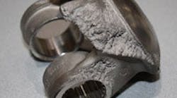
Figure 2. Damage to valve trim component was reproduced under laboratory conditions to show the effect of cavitation.

Sometimes, flashing alone occurs. When the downstream pressure of a control valve is less than the liquid vapor pressure, part of the liquid is vaporized and remains as vapor downstream of the valve. So, fluid downstream of the valve is part liquid and part vapor. Flashing flow may cause mechanical difficulties like erosion and vibration. However, the problems stem from the high velocity of the two-phase flow stream due to the larger vapor volume compared with that of the liquid, rather than bubble implosion. Because flashing generally is the result of unalterable line conditions, it can't be avoided by selection of valve type. High velocity can erode valve body internal surfaces downstream of the throttling point, so use of more-wear-resistant materials is recommended.In practice, to minimize the length of piping downstream, the valve usually is located as close as possible to the receiving vessel. Vertical upward flow should be avoided to prevent any slug flow, which may cause strong vibrations.TELLTALE NOISETypically when noise is present in liquid service, so is cavitation, and roughly to the same degree. Cavitation bubble implosions are the main source of disturbing noise; noise level is directly related to cavitation intensity. In the early stages of cavitation, the noise can sound like sand going through the valve. When the pressure difference across the valve rises, the intensity of the cavitation increases, as does the severity of the noise.Unfortunately, noise not only indicates that cavitation is underway but also that premature valve failure is possible if not likely. In this situation, the horse is already out of the barn; the plant must suffer the consequences of having valves that weren't adequately sized for the service. Fortunately, manual calculations or, better still, expert sizing software can accurately predict cavitation noise. These noise predictions are a good indicator of potential mechanical cavitation damage. If there's a substantial amount of noise, corrosive damage also is likely. Noise alone can't predict that damage, though, because it also depends upon the medium and the valve material.Inaccurately specified flow conditions often result in the failure to size valves and line components appropriately to ameliorate cavitation. It's common practice to add safety factors to flow conditions, sometimes resulting in specified conditions that don't resemble the actual ones in any way. When this is the case, no software can help. In fact, when faced with cavitation, the very first thing to do is to compare specified to actual conditions.Predicting cavitation damage is complicated because it depends upon many factors (e.g., pressure drop, flow medium, valve type and materials). The onset of cavitation is called incipient or partial cavitation, and shouldn't be confused with the start of damage. Incipient cavitation can be used to predict cavitation noise but not damage. The pressure drop needed to mechanically damage valves or piping depends upon the valve type, size and material. Various studies suggest that the lower the recovery of the valve, the closer the terminal pressure drop can be approached without cavitation damage. However, if the pressure differential is very small and the time the valve is exposed to the cavitation is short, there may not be a problem.
ABATEMENT OPTION

Figure 3. This trim uses a combination of approaches to avoid noise and cavitation.

ABATING NOISE AND CAVITATIONBecause the most significant source of control valve noise in liquid applications is cavitation, it makes sense to deal with abatement of noise and cavitation together. There are two basic approaches for dealing with control valve noise and cavitation: 1. Path treatment. This focuses on dampening the noise generated. It reduces the noise radiated by the piping system but doesn't eliminate cavitation inside the valve and adjacent piping.2. Source treatment. This involves modifying the valve and its trim to decrease the cavitation intensity or prevent the existence of cavitation. Source treatment, whenever possible and feasible, is the preferred approach for addressing cavitation and the associated hydrodynamic noise because only it can avoid excessive generation of cavitation bubbles across a wide flow range.Five different methods can be used (sometimes in combination) for source treatment of hydrodynamic noise and cavitation abatement:Velocity control. Regulating the fluid velocity, which is equivalent to controlling the pressure in the valve internals (trim), is an effective means of avoiding cavitation. The aim of this approach is to get the lowest pressure in the valve trim above the vapor pressure for the liquid in question. This is accomplished by selecting valve trim with the optimal recovery coefficient (FL). For example, simply switching from a butterfly to a ball valve would alter the coefficient. If standard trim doesn't suffice, then we can select multistage trim that divides the valve pressure drop into several stages. There are two basic methods for pressure-drop staging:• identical pressure drop across each stage; or• identical minimum pressure in each stage.The first approach requires a constant-flow-area trim. Due to the equal area, the flow velocity in each stage is constant and the pressure drop is equal. The second approach involves an expanding-area trim, in which the pressure drop in the first stages is very high but a higher minimum pressure is maintained in the last stages, thereby better avoiding cavitation within the trim. Expanding-area trim is recommended when extensive reduction of cavitation is necessary. However, the velocity in the first stages of this trim will be quite high and may create erosion problems. In practice, valve designers usually combine the two methods to arrive at an optimum solution.Acoustic noise and bubble size control. The division of flow into multiple small streams actually has two effects: it acts to create a pressure stage and also reduces the size of vapor bubbles in the fluid. Smaller bubbles cause higher-frequency noise fields in the fluid and reduce the external vibration intensity of the pipe as well as the mechanical and erosion effects of cavitation. The concept of using small jets to decrease control valve noise is based on the principle that the jet produces a characteristic frequency above the pipe ring frequency, thereby reducing the sound reradiated by the pipe.Location control. This principle of flow path design directs flow in the valve away from solid boundaries so bubble implosions will have less impact and therefore less potential for causing damage.Flat baffle plates. When the pressure drop ratio becomes very high, it's possible that anti-cavitation trim in a valve won't sufficiently lower the levels of noise and cavitation. In this case, using a baffle plate after the valve can create backpressure to reduce the pressure drop across the valve and thereby minimize noise and cavitation.A flat baffle is a flow restrictor with a custom-made constant flow area and multiple holes for a particular flow condition. The pressure drop across a baffle plate is proportional to the flow squared. Because a baffle plate is a fixed restrictor, it produces the desired pressure drop only at a single flow — the one used for sizing the baffle. A baffle plate typically is sized for the valve maximum flow. As the flow goes down, the pressure drop across the baffle decreases and the pressure drop across the valve increases. Thus, the baffle plate loses its effect at low flow rates.Orifice plates. An orifice plate is a constant flow resistance. It only has one large hole rather than the multiple small holes in a baffle plate. An orifice plate can be used for producing linear valve installed flow characteristic and, in limited cases, for cavitation abatement. An orifice plate can be installed both upstream and downstream of a control valve. Sizing basically is similar to that of a baffle plate.Figure 3 depicts how a Q-trim valve uses a combination of approaches, including multistage pressure drop to lower valve trim velocity and multiple-stream flow to control noise. COMBAT CAVITATIONCavitation can cause severe damage within control valves and nearby piping due to the formation and high-intensity implosion of vapor bubbles immediately downstream of the vena contracta. This mechanical impact damage, along with associated erosion and corrosion, can substantially impair control valve performance, resulting in lower productivity and product quality along with the added costs of product loss, labor and materials when valves fail prematurely.Predicted levels of noise (which always accompanies cavitation) correlate closely with the potential for mechanical damage. Expert sizing software may be used to simulate noise/cavitation levels under actual line conditions to arrive at the most-effective feasible abatement measures. While it may be impossible to totally eliminate cavitation in every instance, its harmful effects and associated costs always can be substantially minimized.


STEVEN HOCURSCAK is North American business manager for Neles & Mapag, Shewsbury, Mass. KYLE RAYHILL is global business manager for Neles & Mapag, Shewsbury, Mass. E-mail them at [email protected] and [email protected].
Sponsored Recommendations

Keys to Improving Safety in Chemical Processes (PDF)

Many facilities handle dangerous processes and products on a daily basis. Keeping everything under control demands well-trained people working with the best equipment.

Get Hands-On Training in Emerson's Interactive Plant Environment

Enhance the training experience and increase retention by training hands-on in Emerson's Interactive Plant Environment. Build skills here so you have them where and when it matters...

Rosemount™ 625IR Fixed Gas Detector (Video)

See how Rosemount™ 625IR Fixed Gas Detector helps keep workers safe with ultra-fast response times to detect hydrocarbon gases before they can create dangerous situations.

Micro Motion 4700 Coriolis Configurable Inputs and Outputs Transmitter

The Micro Motion 4700 Coriolis Transmitter offers a compact C1D1 (Zone 1) housing. Bluetooth and Smart Meter Verification are available.