Select The Right Gas Delivery System
You can take several steps to ensure that your plant’s high-purity carrier, support, process or calibration gases are supplied safely and cost efficiently without compromising purity and sample integrity. Adherence to codes and specifications is vital (see “Properly Deliver Compressed Gases”), as is following a comprehensive series of procedures that also improve efficiency. You also should pick conditions optimal for the specific application and hardware components compatible with the gas.
This article focuses on the two latter considerations, namely:
• pipeline size relative to flow and pressure drop rates; and
• materials compatibility for gas process lines and sampling systems.
Pipe Sizing
[sidebar id="1"]Designers should size piping so that pressure drop at the furthest point in the system doesn’t exceed 10% of the inlet pressure under actual flow conditions. Table 1 lists the maximum flow rate of nitrogen in ft.3/hr. for pipe diameters from 1/8 in. to 3 in. and pressures from 5 psig. to 250 psig. — the data are for 10% pressure drop per 100 ft. for ½-in. and smaller sizes, and 5% pressure drop for larger diameters. To convert this table to the gas of interest, you must multiply the flows by a factor based on the difference between the specific gravity of nitrogen and that gas. While there’re more accurate equations for this conversion factor, you can get a reasonable value by dividing the square root of nitrogen’s specific gravity by the square root of the gas of interest’s specific gravity.
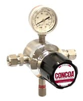
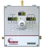
However, this doesn’t provide the entire picture. The source must be able to provide this flow rate at the required pressure. Some gases, such as nitrogen for large process applications, are delivered in pipelines direct from a source such as an air separation plant, while other gases are supplied in high-pressure cylinders or from portable or permanent cryogenic tanks. Source pressure must be reduced to piping inlet pressure using either a simple single-pressure control device (Figure 1) or a computer controlled system that has a primary and backup supply source (Figure 2).
Figure 1. Pressure control:
A simple single-pressure device
can reduce source pressure to
that needed for the application.
Size the source and the pipeline itself with an adequate but affordable safety factor to allow for peak demand and future growth. It’s not unusual to apply a safety factor of two times the current anticipated flow and from 1.2 to two times the required pressures. This provides a margin so future additions or changes in process requirements don’t necessarily demand a totally new piping system.
For a pipeline with more than one use point, calculate flow assuming total flow occurs at the farthest use point from the inlet of the system. This ensures that each point won’t be starved for flow because one high-flow use point creates a huge pressure drop every time it’s initiated. Another way to compensate for disparate flow rates at different use points is to run the entire pipeline in a loop, beginning and ending at the same inlet point, so no point is any further from the supply than any other point. For large piping systems made with exotic materials this can be cost prohibitive but for smaller systems or critical use processes it can make the difference between a system that works and one that doesn’t.
The safety or supply limitations that apply to specific gases is another consideration. With acetylene, for safety reasons (to prevent spontaneous ignition in air) pipeline pressure can’t exceed 15 psig. Certain gases that come from liquefied or cryogenic sources have maximum-flow-capability restrictions. For carbon dioxide, ammonia, chlorine or liquid hydrocarbons like propane, the bulk of the product actually is in the source tank or cylinder in liquid form; the use valve withdraws gas from the vapor phase. This gas must be replaced by vaporizing liquid. Achievable withdrawal rate depends upon both volume and temperature of the liquid.
Check that the bulk supply for these types of gases is appropriate — either by the number of cylinders or the size of both the bulk tank and any external vaporizing device. Table 2 indicates the maximum withdrawal rate in ft.3/hr. for propane based on cylinder temperature and liquid remaining in a 100-lb. cylinder.
Samples for process stream composition or purity usually involve tiny volumes. Keep the pipe diameter as small as possible — 1/8-in. outside diameter or less is common. Also, limit the length from the sample valve to the analyzer and use pressure or flow control devices with minimal internal volumes. This ensures as real-time a sample as possible.
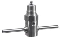
[sidebar id="2"]In drawing gas samples consider source pressure and necessary inlet pressure of the analyzer, along with required sample size or rate. For analytical processes the sample must be delivered as a gas or at a certain temperature. Samples in liquid phase or having condensable components normally need a vaporizing pressure regulator (Figure 3).
Material Considerations
Today’s designers have more materials options than ever. New alloys have greatly extended the life of lines in corrosive service. Improvements in welding processes, joining techniques and fittings have reduced the labor burden and maintenance on many types of installations while improving leak integrity and purity of the resulting systems.
To select piping system material, start by considering properties of the gas and the process or instrumentation. For process and instrumentation gases, maintaining purity is a key requirement. It does little good to purchase high-purity grades of instrumentation gases if the delivery pipeline contaminates them.
All materials chosen should be cleaned to very high levels, delivered to the site capped, and installed by persons using processes capable of maintaining that level of purity. Copper tubing or pipe should be at least “cleaned for oxygen service,” a standard that guarantees it’s as free of hydrocarbon contamination as possible and safe for use in oxygen piping systems. Type 316L and other stainless steels or more exotic alloys benefit from electropolishing although this isn’t required.
Figure 2. More sophisticated option:
A computer-controlled system with a
primary and backup supply source
can adjust pressure to the piping inlet.
For inert or non-reactive gases, it’s now just as expensive to use copper as 316L stainless. So, choose stainless because of its many advantages: it’s generally suitable for even corrosive or reactive gases, the leak integrity of compression-fitting or orbitally-welded joints is far superior, and installation costs are less. For extremely corrosive or reactive sample or process lines, consider high-nickel alloys. System durability and improved safety often outweigh the higher cost.
Piping materials and installation for oxygen deserve special care. At concentrations above 23%, oxygen can be extremely hazardous; even a small amount of a contaminant that won’t ignite in air will burn or virtually explode when exposed to a pure oxygen atmosphere. Therefore, the piping system and components must be certified as cleaned and suitably installed for “oxygen service.” Many facilities require piping systems carrying high-pressure (above 300 psig.) oxygen to be made of Monel, which strongly resists promoted ignition in pure oxygen. Lower-pressure systems that don’t need high-purity components typically use copper pipe that’s silver brazed.
Never use copper for an acetylene piping system because the acetylene will react with the copper to form hazardous and explosive compounds.
Figure 3. Vaporizing pressure
regulator: Such a regulator is
used to transform samples in
liquid phase or with condensable
components into a gas
Fluorine, fluorine mixtures and certain fluorine compounds like hydrogen fluoride require high-nickel alloys or, for some components, pure nickel. All components and piping must be passivated for fluorine service. This involves slowly increasing the concentration of fluorine in the system until the internal surface reaction sites of the piping and its components have a metal fluoride layer that prevents further reaction with fluorine. Any system modification or addition, no matter how minor, necessitates repeating this process.
Glass-coated stainless steel often is an attractive option for highly reactive samples such as multiple-component reduced sulfur samples that are part of many facilities’ EPA-mandated pollution-monitoring requirements. The coating process imparts inertness and corrosion resistance to the substrate; 316L stainless is the most widely treated material but the process suits most stainless steels. Besides tubing, many components including valves, pressure control regulators and various other parts can be coated.
Additional Issues
The maximum allowable working pressure of the material selected should significantly exceed the maximum expected operating pressure — 20% is a reasonable minimum safety factor but 200% is a desirable target. With most wall thicknesses of 300-series stainless steels, this generally isn’t an issue as their working pressure ratings can be as high as 6,000 psig. However, with copper the typical installation is limited to 250 psig.
Installation is the last major issue. Use only qualified and certified professionals. The procedures and testing required to install and certify a high-purity or hazardous process line are somewhat unique. Where practical, compression-type tube fittings speed installation and obviate purging the piping during installation. However, welded connections sometimes are used for higher leak integrity. Any welding or brazing operation demands special care and purging the piping to prevent oxide and contaminant formation. High-purity argon is needed to shield the weld area and continuously purge the piping interior during and until the weld area has cooled; nitrogen typically is the purge gas when brazing copper lines. Thoroughly leak-test the system after installation — ideally with a helium leak detector at each joint. (Using liquid solutions to observe bubbles is a subjective test that only can detect rather large leaks.) Failure to properly install and test the system can lead to extensive additional costs and damage to valuable instrumentation.
Following these simple guidelines and general considerations should result in a system that is delivered under budget, is safe and provides extended service life while delivering high-purity gas and consistent process results.
Larry Gallagher is specialty gas products manager for CONCOA, Virginia Beach, Va. E-mail him at [email protected].
