Squeeze More From Your Process
Imperial Chemical Industries originally coined the term Process Intensification (PI) in the early 1970s for the miniaturization of unit operations. While ICI itself recently disappeared (www.ChemicalProcessing.com/articles/2008/082.html), PI continues to progress.
After all, by using smaller equipment, PI promises to cut both energy use and capital expenditure, decrease plant profile (height) and footprint (area), and provide both environmental and safety benefits.
Earlier (www.ChemicalProcessing.com/articles/2006/176.html), we explored the use of PI for reactors. Now, let’s examine PI’s role in distillation, extraction and heat transfer.
Still opportunitiesFigure 1. Higee distillation columns dramatically reduce the height of a theoretical stage.
Distillation is the most popular separation method by far but also the most energy intensive unit of operation. Conventional columns are often massive and thus costly to build — with the current price of metals, use of 316L stainless steel, let alone exotic alloys, can make a new tower very expensive. So, unsurprisingly, PI has targeted distillation going all the way back to ICI’s pioneering work that led to today’s Higee column (Figure 1).
The Higee is a high gravity rotating contactor with a compact design. It can induce centrifugal forces of more than 1,000 times that of gravity. Higher “g” through centrifugal acceleration gives enhancements in mass transfer and throughput rates by one to two orders of magnitude and, consequently, drastically reduces column size for the same production objective. A torus-shaped rotor spins at approximately 500 rpm. Vapor traffic flows from the outside to the inside of the rotor while liquid traffic flows from inside to outside the rotor. Protensive, Newcastle upon Tyne, U.K., and GasTran Systems, Cleveland, Ohio, provide this technology, which also is known as the rotating packed bed. Currently there are approximately 30 units in operation worldwide; however, many are experimental columns at various universities. Typically Higee reduces the height of a theoretical stage to five centimeters to 12 centimeters from the 150 centimeters to 600 centimeters in a standard column. Packing can be PTFE-coated aluminum sponge for corrosion resistance or other materials.
Higee installations are often used to strip organics from wastewater; Dow Chemical relies on the technology to make hypochlorous acid. Future installations are expected to include various types of distillation applications and retrofits to existing columns.
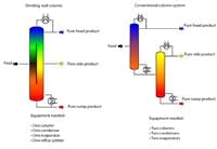
Figure 2. This arrangement avoids the need for a second column with all its attendant costs. Source: Montz.
Another approach intensifies distillation by combining two columns into one, a so-called dividing wall column (Figure 2). This arrangement obviates a second separate column and its evaporator and condenser.
The unit features a vertical wall in the middle part of the column, creating a feed and draw-off section in this part of the column. The dividing wall, which is designed to be gas- and liquid-sealed, permits low energy separation of low and high boiling fractions in the feed section. The medium boiling fraction is concentrated in the draw-off part of the column.
Dividing wall columns can be used wherever multi-component mixtures must be split into high purity individual components. They are well suited for obtaining pure medium boiling fractions (sometimes called heart cuts). For instance, separating a three component mixture into its pure components in conventional systems requires at least two main columns and a side column. In contrast, a single dividing wall column can handle this task — and cut installation costs by 20% to 30% and operating costs by around 25%. This approach also reportedly significantly simplifies process control and reduces maintenance work.
Dividing wall columns have been used commercially to produce chemicals for more than 20 years. One major supplier is Julius Montz GmbH, Hilden, Germany, which now has more than 60 installations.
Academics continue to explore other PI variants for distillation. For instance, the Indian Institute of Technology, Kanpur, India, is developing novel units. In one Higee variant, the overhead condenser, reflux drum and the rectifying section are installed in one common vessel while the reboiler, column sump and striping section are combined in a second common vessel. Thus a complete distillation column looks like two horizontal vessels with dished or hemispherical heads. This reportedly provides a dramatic reduction in installed costs. No commercial installations have been built to date.
In addition, researchers at Carnegie-Mellon University, Pittsburgh are proposing a multi-effect distillation method. The multi-effect approach has been applied to evaporation for years but to my knowledge it’s never been used for distillation, although patents abound. This concept can dramatically reduce the amount of energy required to produce a gallon of product. The University has had a number of inquires but no projects are currently in the development stage.
Essentially a stream to be distilled is split and fed to two columns similar except that one is at high pressure while the other at low pressure. The high pressure column’s condenser serves the low pressure column’s reboiler. Thus the two columns are thermally linked.
Boosting output
Sometimes reaction kinetics limit production. Removing a byproduct can drive the reaction to make more of the desired material. Reactive distillation leverages this by using distillation within the vessel to remove the byproduct.
So, the reaction mixture is heated; then product and byproduct are separated by distillation. In this case, water is continuously removed to force the reaction to the right. When done in a distillation column, the water byproduct comes off the bottom of the column while the methyl acetate product comes off the top.
Some reactions require the use of catalysts inside the distillation column. Methods for introducing the catalyst include: structured packing coated with the appropriate catalyst, trays containing pillows filled with catalyst particles or pillows filled with catalyst particles rolled into bales, and pillows installed between the layers of structured packing.
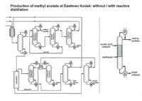
Figure 3. Reactive distillation flowsheet for methyl acetate (right) is far simpler than that of conventional process (left). Source: Eastman Chemical.
Eastman Chemical, Kingsport, Tenn., pioneered one of the first major applications of reactive distillation, to significantly simplify the production of methyl acetate (Figure 3). This unit first went into operation in 1983.
Among the typical reactions where a byproduct prevents the reaction from going to the right are: esterification, transesterification, hydrolysis, acetalization and amination. Other types of reactions that could benefit from reactive distillation include: alkylation/transalkylation/dealkylation, isomerization and chlorination.
We expect installations using reactive distillation to continue to increase at a moderate pace in this decade. Again the driver will be less metal on the ground, ultimately reducing installed costs.
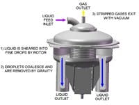
Other separation usesFigure 4. High shear and centrifugal forces create extremely small droplets that enhance dearation. Source: GasTran Systems.
Another application of PI is for removing dissolved gases from process water.
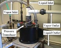
GasTran Systems has developed a novel mechanical approach to single-stage vacuum deaeration to achieve extremely low levels of dissolved gases (Figure 4).
The technology imparts high shear and centrifugal forces on a liquid to create extremely small droplets, thus exposing a large surface area through which efficient gas absorption and gas removal can occur. Once the small droplets are created, a vacuum pump is used to remove dissolved gases to levels reportedly unachievable with other vacuum deaeration designs.
Performance improves with deeper vacuum level; Number of Transfer Units (NTU) values of 4.3 – 4.5 and dissolved oxygen levels of 235 ppb are possible across only a few inches of rotor packing.
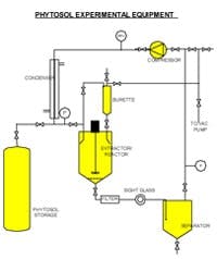
Figure 5. Flash evaporation of low boiling solvents from the extract obviates a distillation column. Source: R. C. Costello & Assoc.
Applications include: dissolved gas removal from boiler feedwater, water for ion exchange and ultrapure services, and many other process water pretreatment jobs. The technology also may serve as a low cost alternative for removal of carrier solvents or a low boiler from reaction products.
Extraction offers another opportunity for PI. Figure 5 shows an experimental system for extracting chemicals from botanicals offered by R. C. Costello & Associates, Redondo Beach, Calif.. This system can be modified to separate organics from water. The technology utilizes low boiling point solvents that are flash evaporated from the extract. Typically 1,1,1,2-tetrafluoroethane is used because it’s very refractory, has a boiling point of -15.3°F (-26.3°C), and isn’t flammable. This eliminates a costly distillation column and related auxiliary heat transfer equipment, pumps and process instrumentation. Combining the approach with a Podbielniak extractor (which most likely was the first PI device invented) can further simplify and miniaturize the extraction system. The Podbielniak could be used to contact the solvent with the heavy liquid instead of using an extraction column.
Hot prospectsFigure 6. No over-sizing to compensate for plugging is necessary thanks to ongoing scouring taking place within this unit. Source: Klaren BV.
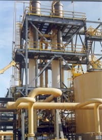
PI already plays a role in heat transfer. For instance, Klaren BV, Hillegom, the Netherlands, offers self-cleaning heat exchangers that require significantly less heat transfer area than traditional shell-and-tube units (Figure 6). The company says that chopped wire circulated through the downcomer and up through the tubes of its shell-and-tube exchanger scour the surfaces clean, removing scale as quickly as it forms. So, there’s no need to oversize the exchanger to compensate for fouling and pluggage.
For one installation, use of the exchangers led to an 80% reduction in surface area and a 60% drop in horsepower. The plant previously shut down for six days each month for heat exchanger cleaning. After installation of the self-cleaning heat exchangers, the plant ran 30 months without a shutdown. This changeover essentially debottlenecked the plant.
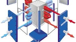
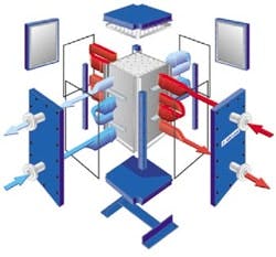
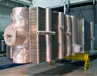
Another contender in intensified heat transfer technology is Alfa Laval Inc., Richmond, Va., with its Compabloc welded plate exchangers (Figure 7), which already have proven themselves in numerous installations. These units feature high surface area per unit volume compared to traditional shell-and-tube heat exchangers. So, they take up considerably less floor space. They also reportedly boast three to five times greater efficiency than shell-and-tube units.
Figure 7. Traditional advantages of plate design are augmented by the elimination of gaskets. Source: Alfa Laval.
The exchangers resemble traditional plate-and-frame units but instead utilize welded construction, thus eliminating the gaskets typically found between the plates. They have a wide range of operating pressures and temperatures up to a maximum pressure rating of 450 psig and 650ºF, and can be supplied in a variety of materials including exotic alloys.
Other features of these exchangers include: total accessibility on both sides; temperature cross capability; and bolted construction for easy access.
Heatric, Houston, produces diffusion-bonded heat exchangers. These units are constructed from flat metal plates into which fluid flow channels are either chemically etched or pressed. The configuration of the channels on the plates for each fluid is determined by the temperature and pressure-drop constraints and heat exchange duty. The channels can be of unlimited variety and complexity. Configurations can be counterflow, crossflow, co-flow or a combination of these to suit the application.
Plates are stacked and diffusion-bonded together to form strong, compact all-metal heat exchange blocks containing the fluid flow passages. (Diffusion-bonding is a solid-state joining process that entails pressing metal surfaces together at temperatures below the melting point, thereby promoting grain growth between the surfaces. Under carefully controlled conditions, diffusion-bonded joints reach parent metal strength.) The blocks then are welded together to form the complete heat exchange core.
Finally, fluid headers and nozzles are welded to the core to direct the fluids to the appropriate sets of passages. No gaskets or braze material — potential sources of leakage, fluid incompatibility and temperature limitations — are required for exchanger assembly. Mechanical design is normally to ASME VIII Division 1. Other design codes can be employed as required.
The majority of diffusion-bonded heat exchangers are constructed from 300-series stainless steel. Various other metals such as nickel alloys and titanium are compatible with the diffusion-bonding process.
Figure 8. These units feature mini-channels that provide high surface/volume ratio. Source: Chart Energy & Chemicals.
Mini-channels feature in the brazed aluminum heat exchangers that Chart Energy and Chemicals, The Woodlands, Texas, has been manufacturing for more than 25 years (Figure 8). These units boast surface areas per unit volume of 300 to 450 ft2/ft3 (1,000 to 1,500 m2/m3), which is six to 10 times higher than that of a comparable shell-and-tube heat exchanger. They can have up to 10 inlets and outlets — offering the potential to combine numerous heat exchanger services into a single compact unit and thus cut costs for engineering, installation, insulation, testing, etc.
The units allow temperature approaches as low as 2°F (1°C), resulting in lower compressor horsepower requirements and lower plant operating costs.
The heat exchangers have been used in cryogenic applications because the 100% aluminum construction can withstand temperatures as low as -452°F (-269°C) and pressures as high as 1,750 psig (120 bar g) or more. In addition the high thermal conductivity of aluminum coupled with the enhanced heat transfer performance of plate-fin construction reportedly produces as much as 20 times greater heat transfer performance (UA) than shell-and-tube exchangers of equal size. This higher efficiency can translate into a heat exchanger costing approximately 25% to 50% less and weighing 95% less than a stainless steel shell-and-tube exchanger.
The value of PI
Novel process-intensified unit operations create a new palette of tools for process engineers to design lower cost plants. Savings are achieved by putting less iron on the ground. Additionally, these less expensive plants can simplify production by reducing the number of unit operations, boost product purity and cut operating costs — clearly words that corporate management wants to hear. Process intensification isn’t futuristic or pie-in-sky but is here now.
Rocky Costello is president of R. C. Costello & Associates, Inc., Redondo Beach, Calif. E-mail him at [email protected].
