Upgraded Cooling System Halves Energy Costs
|
Related Articles Chill out about cooling costshttp://www.chemicalprocessing.com/articles/2007/128.html Cast a cold eye on columnshttp://www.chemicalprocessing.com/articles/2008/075.html Who You Gonna Call When Primary Cooling Fails? |
Cooling water plays a crucial and varied role at many plants — from temperature control of exothermic reactors to removal of pollutants via vent condensers. Sites require a reliable supply to maintain production and often to avoid safety and environmental incidents. Batch operations, with their many startups and shutdowns, pose an additional challenge in ensuring that cooling water is available when and where it’s needed. Such units, especially in pilot plants, may stay idle for an extended time. When they run, cooling demand can change from nonexistent to peak capacity within just a few minutes.
So, most companies will opt for a cooling system that has excess capacity. But with today’s high energy costs, too much excess capacity can lead to a loss of competitive advantage. It’s therefore critical to find a reliable, capable and economical source of cooling water.
Recently King Industries faced this challenge. Because our plant has variable production demands, it was important to install a system that was responsive to process demand yet energy efficient. Our upgrade gave us more cooling capacity while cutting energy costs by more than half.
Design basis
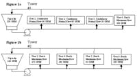
Figure 1. Cooling system had two sections served by separate pumps.
The plant’s existing cooling system included two towers, each with a centrifugal circulation pump operating at constant 3,500 rpm. The first tower fed three continuously operated units and a fourth batch unit that was infrequently used (Figure 1a). It provided up to 330 gal/min of cooling water. The second tower fed four batch units in a pilot plant area, each with highly variable demand (Figure 1b). This second tower provided only 120-gal/min peak capacity, which severely limited operations. Each tower had a fan equipped with a 5-hp motor spinning at 1,750 rpm.
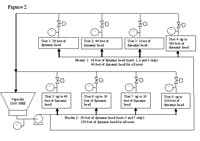
Demand for pilot plant operations increased, necessitating a boost in cooling water flow to the area. So, we decided to replace the two towers with a single new one capable of providing cooling water to all eight users (Figure 2). Given current labor and business limitations, however, the cooling system would rarely run at maximum capacity. So, it was essential that it operate as economically as possible at varying capacities.
Our engineers evaluated each process unit, targeting a maximum cooling water temperature increase of 10°F. For continuous units, they used the normal energy removal rate to determine required cooling water flow (given in Figure 1a). For batch units, they calculated maximum cooling water flows (Figure 1b). This totaled 860 gal/min for the eight units, or 72% more flow than the original two tower system. We then applied a modest 20% factor to allow for any future expansion or contingency. This brought the targeted maximum flow rate for the new system up to 1,030 gal/min or 106% more than the original two tower system.
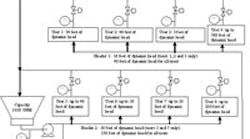
Figure 2. Single pump with VFD provides greater flow at lower cost.
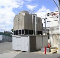
We then sized the cooling tower itself. Based on the proposed circulation rate of 1,030 gal/min and a 10°F temperature rise, we determined the maximum heat removal rate for the tower to be about 5.15 MM BTU/hr, or 430 tons. With the help of the manufacturer we chose a tower based on this maximum heat removal rate and the maximum expected wet bulb temperature for the geographic area. The new tower included two air circulation fans equipped with 5-hp inverter duty motors capable of spinning at up to 1,750 rpm.
The next step was to determine how much pressure rise, or total dynamic head (TDH), the circulation pump needed to generate to provide this cooling water circulation rate. Total dynamic head (TDH) is the sum of overall elevation change (i.e., static head) and friction loss (i.e., dynamic head). The system returned cooling water to an open air-cooled tower. Thus, the difference in height between the pump suction and the tower return line gave the static head, in this case, 15 ft. Dynamic head loss in piping systems is a function of flow rate, pipe size, pipe length, piping configuration and components — we found the overall flow resistance at the normal system flow rate of 570 gal/min to be about 100 ft.
So, the centrifugal pump needed to generate about 115 ft of head at this flow rate. The pump would need to produce significantly more head if every user were demanding cooling water at its maximum flow; however, we deemed this scenario unlikely. Instead, we chose a pump based on a reasonable compromise, generation of about 120 ft of head at 1,000 gal/min. It’s equipped with a 50-hp inverter duty motor capable of spinning up to 1,750 rpm. Installing a larger impeller would enable the pump to generate additional TDH, if needed at a later date.
Effective control
Many companies have realized significant energy savings by adjusting speed in response to varying process demand. So, we opted to use variable frequency drives (VFD) on both the circulation pump and the cooling tower fans to help maximize efficiency.
We adopted a simple strategy to adjust cooling water flow in the various branches. We use cooling water supply and return temperatures as measures of the energy removal rate within a process, and aim to control cooling water flow within a branch to target a rise of 10°F.
To accomplish this, a temperature element and control valve were installed on each of the eight branches on the return line to the main header (Figure 2). A temperature element also was put on the supply line near the circulation pump. This allowed for the continual measurement of temperature rise for each of the eight units being fed.
Each control valve is forced to stay open at least 20%, to provide a minimum amount of flow through each branch. As cooling water within a particular branch rises more than 10°F above the supply temperature, its flow control valve opens further. This allows for greater flow through the branch needing water, slightly reducing flow through the other seven branches as resistances to flow change.
As demand within a branch continues to rise, the valve continues to open. The control system continually monitors the positions of all eight control valves. If any valve opens more than 80%, pump speed increases. As pump speed rises, so does flow and total dynamic head generated. This increase in head results in greater water flow through all branches. If a branch doesn’t require greater flow, its control valve closes (to its minimum position of 20%, if necessary). This directs more flow to the branch in need. The pump speed is set to run at a minimum of 975 rpm, to ensure some flow through the system.
The VFDs on the air circulation fans in the cooling tower allow us to compensate for changes in cooling water supply temperature, which can vary seasonally from near freezing to 80°F or higher, by altering speed. The old setup also used two 5-hp fans but both operated continuously at 1,750 rpm.
The new fans are programmed to operate from 25% to 100% of maximum speed over a 25°F temperature range, which differs for each: 45°F to 70°F for one, and 50°F to 75°F for the other. A two degree dead band prevents each of the fans from cycling on and off. Each of the fans shuts off at two degrees below its low point temperature (43°F and 48°F, respectively) and restarts once the temperature rises to the minimum value. When the supply temperature exceeds the maximum value in the range, the fan remains operating at full speed.
The incremental capital investment for these controls was estimated at $68,200 ($41,700 for equipment, $15,000 for labor and $11,500 for engineering). We also used this project to introduce fieldbus technology to the plant, which boosted the total capital expenditure for the controls to $102,400. However, the plant was able to take advantage of an incentive program offered by our electrical utility company. It provided one half of the initial estimated investment, or $34,100. Thus, our actual capital cost for the project was $68,300.
Impressive results
| Significant savings | Old System | New System | Change |
| Circulation pump(s) | 2 | 1 | -1 |
|
3,500 rpm (constant) |
1,750 rpm (maximum) | |
|
450 gal/min total | 660 gal/min average | +47% |
|
12.4 kW (estimated) | 6.9 kW (average) | -44% |
| Tower fans | 2 | 2 | 0 |
|
1,750 rpm (constant) | 1,750 rpm (maximum) | |
|
6.1 kW (estimated) | 1.3 kW (average) | -79% |
| Total system | |||
|
18.5 kW (estimated) | 8.2 kW (average) | -56% |
|
$21,100/yr | $9,400/yr | -$11,700 |
Table 1. Speed controls on pump and fans enable steep cuts in operating costs. |
|||
The new tower system has been operating for more than one year. During that time, we have monitored speed and power consumption for the circulation pump and tower fans. These data show that, while the system provides about 47% greater flow, annual operating costs have been cut by more than half, based on current electricity charges of $0.13/kWhr and 8,760 hr/yr. Pump power draw has dropped by almost 45%, while fan power draw is down by nearly 80% (Table 1), thanks to use of VFDs.
We estimate the overall energy savings for this project at $11,700. So, based on the capital cost of $68,300 and an assumed project life of 20 years, we achieved a 13.8% discounted cash flow rate of return. Had we not received the electric company incentive, the total cost for controls of $102,400 still would offer an 8.4% rate of return. We also should realize additional non-quantified benefits:
- Slower motor speeds should increase equipment reliability and decrease maintenance costs
- Fewer pieces of equipment should reduce future costs for replacement parts
- The potential for significant increases in plant capacity and productivity because average speeds are far below maximum values
Overall this project met its three objectives of providing a reliable, capable and economical source for cooling water. The simplicity of the control scheme has worked well and should be adaptable to other systems within the company and throughout the process industries.
Peter Montagna is engineering manager for King Industries, Inc., Norwalk, Ct. E-mail him at [email protected].
