Don't err with Air Compressors
|
Related articles Compressed Air Systems: The Secret is in the Pipe Give your compressors a boost |
Chemical plants vary widely in size and complexity — and so do the types of compressors used in them, and the compressors’ capacity control systems. The units often differ significantly from those at most industrial manufacturing plants using compressed air, where the most common compressor now is the oil-injected rotary screw.
While chemical plants generally pose less variation in flow requirements from shift to shift than other manufacturing facilities, there can be differences in pressure requirements for the various processes, plus instrument air. Air quality requirements, including dryness, also may be stricter for some processes, requiring different drying and filtration methods. Each of these aspects may require segregation of some systems for more efficient operation. In addition, the cost of loss of production, due to an interruption of air supply, must be considered. We’ll look at these considerations.
Demand profile
It’s essential to know how, where and in what quantities compressed air is being used. List each process or application, together with the minimum, average and peak rates of flow and any cycle times on and off. Staggering the timing of peak demands can reduce the total maximum demand. One common problem is that distribution piping is sized for the average demand, with pressure drop based on that. When peak demand is significantly higher, the pressure drop also will be significantly higher, resulting in a lower pressure at the point of use or requiring a higher discharge pressure from the compressor(s). So, size distribution piping for the peak flow rate with an air velocity in the pipe not to exceed 30 ft/sec.
Also, establish the required operating pressure for each process or application. Significant differences in required operating pressure may identify potential segregation of processes or applications for overall system efficiency. Operating the total compressed air supply at the highest required pressure results in increased power consumption (an approximately 1% increase for every 2 psi). Having a separate air supply at the required pressure for a specific process or application can improve overall system efficiency. In each case, ensure that sufficient backup air supply is available.
While adequate primary compressed air storage (near the compressors) is essential for efficient capacity control of the units, adequate secondary storage (near each point of use) can prevent wide swings of pressure at each point of use.
Compressed air leakage in the distribution system also contributes to the cost of operation. Leak detection equipment is readily available and an ongoing leak detection and repair program should be standard practice. In addition, idle production machines or processes should be fitted with shut-off valves that close upon shut down.
Adequate pressure sensing points must be available from compressor discharge, before and after dryers and filters and throughout the distribution system to each point of use. This can allow monitoring the dynamic variations in the entire system.
Compressor types
Three kinds of compressors generally find use at chemical plants:
- Centrifugal. Larger plants often use centrifugal compressors, which are capable of substantial flows of air, although they’re now available in as low as 100 hp. These are dynamic compressors, where a continuous flow of air has its velocity increased by impellers rotating at high speeds. The velocity energy, or kinetic energy, is translated into pressure energy in diffuser or volute chambers. The number of impeller stages depends upon the desired final pressure and efficiency. Cooling occurs between each stage. An important advantage of centrifugal compressors is that they are inherently oil-free, with no lubricant coming into contact with the air passing through the compression process. They generally are water-cooled.
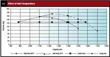
Figure 1. Reduced capacities in centrifugal compressors can lead to a reversal of flow.
Centrifugal compressors have a characteristic pressure curve, where pressure increases as capacity decreases. This is an important consideration in capacity control, which is further complicated because pressurehead- making ability varies inversely with absolute inlet temperature and resultant mass. This means that, when designed for a given inlet capacity in actual cubic feet per minute (acfm), the mass flow increases inversely with absolute inlet temperature and the pressure generated also increases because of the denser inlet air. So, for a given discharge pressure, the compressor will have “grown.” See Figure 1, which presumes the same inlet temperature to each stage. Cooling water temperatures can further affect the curve. Figure 1 has a control pressure of 125 psig. It also shows a “surge” line, to the left of which, at reduced capacities, a flow reversal can occur and should be avoided.
Generally, plants want to maintain a relatively constant pressure to the system; controls will reduce capacity if the pressure tends to rise above the set point due to decreasing demand. With centrifugal compressors, a common means of capacity reduction is by progressively closing an inlet valve or guide vanes. This causes a pressure drop at the compressor inlet, reducing the mass flow in proportion to the absolute inlet pressure. Because inlet guide vanes impart rotation in a similar direction to the impeller, this provides energy savings compared with a simple butterfly valve. However, as stated, flow reduction must be limited to avoid surge and generally flow shouldn’t go below 80% or 70% of capacity.
The biggest potential energy problem is when further capacity reduction requires opening a blow-off valve, discharging already compressed air to atmosphere. This should be avoided. Some centrifugal compressors can be unloaded at this point to keep from wasting compressed air. Some units also can be run in a load/unload mode. Unloading involves closing the inlet valve and discharging the substantially reduced minimum flow to atmosphere, resulting in an unloaded power of approximately 15%. The bearing designs must be capable of running in this markedly reduced mass-flow condition; any desired change in capacity control should be discussed with the manufacturer to avoid potential problems.
Advantages of centrifugal compressors include:
- oil-free air delivery
- generally well packaged and no need for special foundations
- relatively smooth air delivery
- relative first cost per cfm or hp improves with size.
Disadvantages include:
- limited constant discharge pressure capacity control range
- need for specialized bearings for high rotational speeds and monitoring of vibrations and internal clearances.
At full capacity and 100-psig discharge pressure, operating cost typically runs 16–20 kW/100 cfm.
- Rotary screw. Many chemical processes require oil-free air, so oil-free compressors are popular. Oil-injected compressors sometimes are used with additional clean-up equipment including specialized filtration — but this adds pressure drop, mandating a higher compressor discharge pressure than otherwise would be needed.
The oil-free rotary screw compressor generally requires two stages of compression, with inter-cooling, for pressures in the 100–150 psig range. Capacity reduction on constant speed compressors by inlet valve throttling is limited to about 80% of capacity, due to increasing discharge temperature. Below this it’s necessary to unload the compressor. Ample storage capacity then is required. Compressors with variable speed drive (VSD) provide more flexibility in capacity reduction.
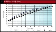
Figure 2. Oil-injected rotary screw compressors require ample capacity to avoid cycling with this type of control.
Oil-injected rotary screw compressors can use various means of capacity control. The most common but least energy efficient is by inlet valve throttling. At about 40% of capacity, the power requirement is more than 80% of full load power. Below 40%, the compressor is unloaded, with no flow to the system, but will then require about 25% of full load power. Again, ample storage capacity is required. Load/unload (full capacity/zero capacity) control can cause excessive cycling unless ample storage capacity is provided (Figure 2).
Some models are available with variable displacement, which provides capacity control by changing the effective length of the rotors. This offers some improvement over inlet valve throttling but also is limited in the capacity control range.
Figure 3. VSD oil-injected rotary screw compressor provides more efficient capacity control than possible with constant speed unit.
VSD rotary screw compressors provide much more efficient capacity control, although they sacrifice a bit of efficiency at full capacity. Compare the percent power at various capacities (Figure 3), with the comparable data for inlet throttling (Figure 2).
For the oil-free rotary screw compressor, advantages include:
- complete compact package
- relatively low first cost
- no need for a special foundation.
Disadvantages include:
- less efficiency than water-cooled reciprocating type
- higher long-term maintenance costs.
Its operating cost at full capacity and 100-psig discharge pressure runs 18–22 kW/100 cfm two-stage. For the oil-injected unit, advantages include:
- complete compact package
- relatively low first cost
- no need for special foundation
- routine maintenance (oil, filter, separator changes).
Disadvantages include:
- less efficiency than water-cooled reciprocating type
- potential problem of oil carryover.
Operating cost at full capacity and 100-psig discharge pressure runs 18–19 kW/100 cfm single stage and 16–17 kW/100 cfm two-stage.
- Reciprocating compressors. These units come in single-acting and double-acting configurations. The single-acting type uses only one side of the piston to compress the air, whereas the doubleacting uses both sides. Single-acting compressors generally are small in size, air-cooled, and limited in capacity and time of operation but can be conveniently located near the point of use. Double-acting units usually are water-cooled and can have two or more stages of compression, which increases efficiency. They also can have multiple steps of capacity reduction, providing 100/75/50/25/0% capacity within a specified pressure control band. Both lubricated and non-lubricated piston/cylinder versions are available.
The advantages of double-acting compressors include:
- efficient compression
- efficient multi-step capacity control
- relatively routine maintenance.
Disadvantages include
- relatively high first cost
- need for special foundations due to vibrations
- oil carryover on lubricated versions.
The operating cost at full capacity and 100-psig discharge pressure for a water-cooled double-acting unit runs 15–16 kW/100 cfm. In contrast, an air-cooled single- acting compressor runs 22–24 kW/100 cfm.
Multiple compressors
Many plants link together a number of compressors into a single compressed air system. In such a system, all compressors but one should be operated at full capacity and optimum efficiency. The one so-called trim compressor is capacity controlled to satisfy system demand at a relatively constant pressure. This also minimizes the amount of storage capacity required. Sophisticated sequencing control panels can allow a change of trim compressor to even out run time and changes where demand varies from shift to shift. The limited capacity control range of many centrifugal compressors restricts their capability as trim compressors. Constant-speed oil-free rotary compressors have similar limitations but those with VSD are capable of a wide range of capacity reduction. Oil-injected VSD rotary compressors also are available. VSD compressors can maintain a supply pressure within ±1 psi. (Centrifugal compressors don’t come with VSD because the pressure-head-making capability varies as the square of the rotating speed and the required discharge pressure can’t be maintained at the reduced rotating speeds.)
Pressure/flow controllers also can be used to provide a relatively constant supply pressure (±1 psi) while demand varies but may require an increased compressor discharge pressure. Where used, they should be located downstream of the primary air dryers(s) and primary air receiver. The controller should be guaranteed by the supplier for operation over the entire anticipated range of rates of flow.
The same considerations apply to multiple compressors in different systems. The advantage of separated systems is that each can have its compressor(s) and compressed air treatment equipment tailored to the specific required conditions of operation without being influenced by the requirements of another system. One potential disadvantage is the need for adequate standby compressors and treatment equipment in each system. When systems are segregated to allow operation at different pressures, it’s possible to arrange for supply from a higher pressure system to a lower pressure system in times of emergency — provided the higher pressure system is adequately sized.
Air quality
Whichever type of unit provides compressed air, it’s crucial to ensure the quality of air suffices for its intended use. Process equipment manufacturers often note air quality requirements. Where this isn’t given, ask the vendor to specify the necessary level, preferably with reference to a published standard. ISO 8573-1 is the International Standard for Air Quality Classes. It defines allowable levels of solid particles, moisture and liquid condensate, and lubricants. In some environments hydrocarbon gases can be ingested at the compressor inlet, so that the air delivered may not be truly oil-free and may require appropriate filtration.
A major consideration in many chemical plants is the quality of the product(s) being produced and the compressed air that comes in contact with it. As a general rule, air shouldn’t be dried more than required for the given application. This avoids unnecessary operating and maintenance costs. However, the limitations of compressed air drying equipment should be understood.
Refrigerant-type dryers cool the air to allow condensate to be drained off but at 32°F freezing will occur, so drying is limited to a pressure dew point of 35°F to 38°F. While this is adequate for many industrial applications, it generally doesn’t suffice for many chemical processes.
Standard regenerative-desiccant-type dryers use a material that adsorbs moisture and provide a pressure dew point of -40°F. Others are available down to -100°F. This type of dryer generally has twin towers, allowing one tower to be drying the compressed air going to the system while accumulated moisture is being removed from the desiccant in the other. Some dryers use heated purge air; a cooling option may be needed where processes are temperature sensitive. Specify a dew-point-sensing controller. A standby dryer allows for maintenance without shutting down the process. In segregated systems, drying can be tailored to meet the specific needs of the system.
As with drying, filter only to the extent needed for the particular process. Use ISO 8573-1 to determine the appropriate classes. There are three basic types of filtration: particulate, coalescing and adsorption. Specific applications may require combinations of types.
Key resources
|
One common problem is that filters may be sized to match the size of the piping in which they are to be installed. The anticipated system flow rate should match the recommended flow rate of the filter. Determine piping size not by the size of the filter connections but by the anticipated maximum system flow rate, with a pipe velocity not to exceed 30 ft/sec.
Locate filters where they can be readily serviced; arrange standby filters, with bypass valves, to allow continuous operation during maintenance.
Install a good differential pressure gauge across filters and take regular readings to establish trends for scheduled maintenance.
David M. McCulloch is principal of Mac Consulting Services, Pittsboro, N.C. E-mail him at [email protected].
