Improve Your Continuous Emissions Monitoring
Industrial-scale combustion processes invariably fall under some form of air-quality environmental regulation, which can take a variety of forms depending on the application and pollutants involved. For instance, the European Union’s Industrial Emissions Directive and U.S. Environmental Protection Agency (EPA) regulations mandate continuous measurement of the relevant pollutants at the point of release to the atmosphere. The EPA notes:
“A continuous emission monitoring system (CEMS) is the total equipment necessary for the determination of a gas or particulate matter concentration or emission rate using pollutant analyzer measurements and a conversion equation, graph, or computer program to produce results in units of the applicable emission limitation or standard.
“CEMS are required under some of the EPA regulations for either continual compliance determinations or determination of exceedances of the standards. The individual subparts of the EPA rules specify the reference methods that are used to substantiate the accuracy and precision of the CEMS.”
A CEMS serves the single purpose of monitoring emissions for regulatory compliance and is not connected to any process control mechanism, although its data may be used to help evaluate combustion processes.
Here, we will focus on the types of installations frequently found in chemical plants and refineries: fired heaters, boilers and some heat-intensive processes. For the most part, these burn natural gas, oil or a combination of plant byproducts. Each generates a list of pollutants connected with these fuels, primarily:
• nitrogen oxides (NOx);
• sulfur dioxide (SO2);
• carbon monoxide (CO);
• carbon dioxide (CO2);
• unburned hydrocarbons;
• ammonia (NH3), usually residue from a NOx suppression system; and
• particulates.
Other applications and fuels may result in a longer list of pollutants requiring monitoring — but these tend to be more specialized.
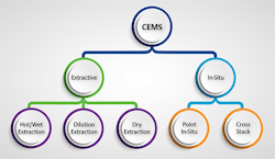
Common to all applications is the need to analyze the flue gas after it has received any treatment and as it is leaving the stack. Two main groups of analyzer techniques (Figure 1) suit this task:
Figure 1. Extractive and in-situ methods can provide continuous emissions monitoring but in-situ approaches suit only a small segment of applications.
1. in-situ, where the analyzer is incorporated into the stack; and
2. extractive, where sample gas is drawn from the stack and sent to the analyzer.
In-situ approaches represent a very small segment; so, this article focuses on extractive methods, which differ in the type of analyzer technology and sample gas treatment. In particular, we concentrate on high-performing newer methods that are much simpler than older technologies and address operational and maintenance problems they pose.
Challenges With Extractive Methods
As it leaves the stack, flue gas primarily comprises nitrogen, residual oxygen, various pollutants, and a lot of water vapor (8–20%). Because the gas is hot, typically >95°C (>200°F), its ability to carry water vapor is greater than air at the ambient temperature. Therefore, the dew point of the flue gas generally is below its exit temperature but higher than the ambient temperature, so water condenses as it reaches the atmosphere.
If sample flue gas being sent to the analyzer is allowed to cool, two things happen. First, water vapor condenses. Second, some of the pollutants of interest, such as SO2, dissolve into the water, which reduces their level in the gas reaching the analyzer and causes understating of their content. (The condensate also becomes acidic and, therefore, corrosive, which can pose issues.)
As a result, to ensure an accurate measurement by the analyzer, extractive methods must have a strategy and mechanism for handling the sample gas in a way that preserves the actual pollutant content. Moreover, the sampling system must present the sample in a way the analyzer can handle.
Let’s now look at the three options.
Dilution extraction. This mixes untreated air with the flue gas to increase its volume and provide cooling. The underlying idea is that the higher volume supplies enough air to avoid condensation, even at a lower temperature. The additional air volume is measured and pollutant levels adjusted accordingly. However, maintaining consistency is difficult because it requires very accurate measurement of sample and dilution air flows, and impurities in the dilution gas affect the readings. This approach mainly finds use for coal-fired applications where water vapor content is low.
Cold/dry CEMS. The most common extraction method for applications at chemical plants and refineries, it has been utilized for many years, so regulations frequently specify this approach or at least assume its use.
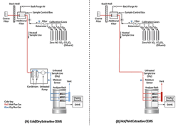
Cold/dry methodology (Figure 2A) passes the sample stream through a thermoelectric chiller to reduce the temperature to about 4°C (39°F), so most moisture condenses and drops out. This approach is mechanically complex but well-suited to an application such as a boiler fired with pipeline natural gas, where the primary pollutant is NOx. Unfortunately, it has problematic side effects, particularly with more-complex fuel situations and longer lists of monitored pollutants.
Figure 2. These diagrams from an U.S. EPA field audit manual illustrate the two most common extractive approaches. A cold/dry system (A) cools the sample gas but doesn’t suit all pollutants. A hot/wet system (B) eliminates the need for cooling the sample gas. Source: U.S. EPA.
Some pollutants, particularly particulates and some acids, are water miscible and dissolve or get captured with the condensate — and, thus, are effectively washed from the sample. This drastically reduces their concentration and makes the readings for those analytes ineffective. Therefore, in situations that require monitoring of water-miscible pollutants (NH3, HCl, HF), this approach is not suitable. Other analytes (NO2, SO2) are somewhat water miscible, so water removal can affect them; however, the error usually is quite small and regulatory bodies often are willing to accept a compensated reading from the dry gas sample.
Hot/wet CEMS. As analyzer technologies have evolved, some have become more tolerant of higher operating temperatures, making the need for chilled gas samples less important. This has helped launch a simple and effective sampling technique that is becoming more widely used: a hot/wet system.
Figure 2B shows a single sample stream flowing directly from the tap point to the analyzer without passing through a chiller. The sample stream is maintained as hot as necessary to keep all components above their dew point, so no condensation occurs. Where high concentrations of SO2 exist, the required temperature can be held at 160–190°C (320–375°F) to stay above the acid dew point.
All chemical components remain in their gas phase, just as they are in the flue-gas stream, during and after passing through the analyzer. When finished, the sample is vented, still as a gas, so there is no liquid at all in the system. The data processing system for the analyzer converts the wet readings to a dry basis as necessary (more on that point later). This approach is less complex mechanically than an equivalent cold/dry system, and calls for different analyzer technologies for some pollutants.
Analyzer Types
Traditional cold/dry systems generally use a combination of established analyzer technologies suited to specific pollutants, including:
• non-dispersive infrared (NDIR) spectroscopy (CO, CH4, SO2, NO, NH3);
• non-dispersive ultraviolet (NDUV) spectroscopy (NO2, SO2);
• gas chromatographic (GC) analyzer (H2S, sulfur species);
• paramagnetic analyzer (O2); and
• chemiluminescent analyzer (NOx).
Some of their capabilities overlap, so individual situations determine the selection of the specific technologies. In certain cases, the regulatory agency may drive the choice in one direction or another. For example, chemiluminescent analyzers long have served as the standard reference method (SRM) for NOx monitoring by the U.S. EPA (Method 7E Procedure) and are cited in standards, e.g., the European Standard EN 14792:2017, used by other regulatory agencies. The SRM is not necessarily the only permissible technology — however, regulatory bodies will insist that any proposed alternative must perform as well as the standard. Therefore, when considering a different technology to measure NOx, it is important to determine if it can cover the necessary range, particularly at the low end, and if the regulations require measurement of all NOx components separately or if they can be lumped together.
A mix of technologies needed to cover multiple pollutants can create operational and maintenance headaches because each may have different consumables, range limitations and calibration requirements. Of course, analyzer technology is not static; established techniques receive improvements, often built upon better data processing and simplified operation. In some cases, preferences for measuring a given pollutant change as less-complex and more-economical technologies emerge.
For example, quantum cascade laser (QCL) and tunable diode laser (TDL) analyzers are growing in popularity thanks to their ease of operation and ability to measure a wide variety of analytes. Generally, QCL covers the mid-infrared spectra while TDL handles near-infrared spectra. Both apply properties of the Beer-Lambert Law for absorption spectroscopy. These two technologies, working together, can cover the full range of the other technologies just mentioned, and provide measurements of all the pollutants common to CEMS applications.
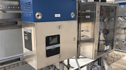
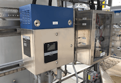
Figure 3. A hybrid QCL/TDL analyzer, such as Emerson’s Rosemount CT5100 Continuous Gas Analyzer, can contain up to six laser modules, some of which can measure two analytes.
Analyzer selection will depend on the complexity of the particular application. For example, a fired heater fueled exclusively by natural gas only may need to monitor NOx, so a single dedicated chemiluminescent analyzer might suffice. On the other hand, the same fired heater, if supplied with a range of fuels, including raw refinery fuel gas, may require monitoring of a wider range of pollutants. A single analyzer able to handle a longer list of analytes might be the better choice for this type of application rather than two or three separate analyzers using different technologies.
Hybrid Analyzers
Laser-based analyzers using a hybrid approach can be modular, with the QCL and TDL measuring cells configured as insertable units into an analyzer. An enclosure (Figure 3) can house a mix of up to six laser modules selected to cover the relevant analytes. Some lasers can measure more than one analyte, so one unit can deal with up to nine analytes; this covers the full range of CEMS applications in a typical chemical plant or refinery application. Laser measuring cells can handle sample gas temperatures up to 190°C (375°F), making them well suited for hot/wet sampling systems.
The use of these laser-based analyzers is increasing for several key reasons:
• Lasers are very stable; there is little need for calibration, although some regulations require periodic verification.
• Absorption characteristics do not change; lifetime sensor drift stays less than 2% of full scale.
• There are no moving parts.
• Laser modules are field replaceable.
• Sophisticated electronics provide extensive diagnostics and remote access.
A Success Story
A refinery in the U.S. Midwest had a tail-gas stream with particularly heavy sulfur content. Rather than simply neutralizing the pollutant, the refinery decided to use a Claus scrubber with an ammonium thiosulfate process to create agricultural fertilizer as a separate product stream. Based on typical production, the refinery anticipated it could manufacture 100,000 tons of fertilizer annually from the pollutant. As part of the installation, the EPA called for a CEMS at the stack to measure residual amounts of SO2 and NOx not captured by the scrubber.
The facility’s environmental engineering team selected Emerson’s Rosemount CT5100 Continuous Gas Analyzer, a hybrid QCL/TDL analyzer working with a hot/wet gas sampling system.
Sample gas is delivered to the analyzer at 125°C (260°F), safely above the water and acid dew points for the flue gas. (Scrupulous heat tracing and insulation avoid any cold spots where condensates could form.) The analyzer contains six laser modules (one TDL, five QCL) configured to measure O2, CO, NO, NO2, SO2 and H2O.
The analyzer converts the wet-basis measurement to dry-basis using an integral water-compensation algorithm. All measurements, including water, are continually checked and corrected during normal operation. After three years of operation, the facility’s environmental team evaluated the system’s performance and found the calibration remained within 1% of the factory settings, with no unplanned outages and required servicing. This fulfilled one key company objective — reducing the amount of maintenance attention required with previous approaches.
It also fulfilled larger corporate objectives to improve energy efficiency and decrease emissions by investing in new technologies and equipment upgrades. Thanks to this and other similar projects, the refinery has reduced emissions over the last 15 years, with its emissions per barrel approximately 20% lower than other refineries in the U.S.
Practical Considerations
Any facility thinking about installing a hot/wet sample-handling system should keep two key aspects in mind.
First, the sample gas must not be allowed to cool. All the tubing, valves, eductors, pumps and other parts of the sample train must remain above the relevant dew point (which mainly depends upon the specific flue-gas composition). Streams with high acid content have a high dew point and, so, are particularly critical. Also, the temperature at the stack where the sample is extracted can vary widely based on a variety of factors but the equipment must be able to withstand the highest potential temperature.
Equipment installers must take particular care with insulation and heat tracing because the sample stream has a very low thermal mass, so its temperature can drop very quickly when passing through even a few inches of unprotected tubing. Heat tracing often requires closed-loop control to keep the sample temperature stable during changing ambient conditions. Any condensation is harmful to virtually all types of gas analyzers, so this is a very critical part of any installation.
Second, a hot/wet measurement usually will result in different values for critical analytes than a cold/dry measurement. This stems from removing the water from the stream, which affects analyte content. It is a quantifiable and predictable change and, therefore, convertible while retaining the necessary degree of precision. However, users must ensure the analyzer includes this capability.
Because cold/dry systems have been the default for so long, most regulations call for dry measurement. Consequently, when a hot/wet application is commissioned, it is necessary to build in a correction factor based on water content of the stream, which requires including a water measurement from the analyzer. Fortunately, many analyzers can make the correction in real time and provide critical analyte measurements on a wet and dry basis.
Avoiding Complexity
All things being equal, chemical plants and refineries understandably choose the simplest and most-reliable approach to solving any application challenge. Historically, analyzers and sample handling systems have been complex and fussy, calling for lots of maintenance attention and consumables. Fortunately, technologies have advanced, becoming simpler and easier to operate than their predecessors. In particular, the combination of hot/wet sampling systems and QCL/TDL analyzers has improved performance and stability for CEMS installations.
To the EPA and other regulatory bodies around the world, the key word in CEMS is continuous. These systems must do their job any time the process is running. If fuel is burning, the CEMS must be working or the facility will be liable to fines, shutdowns and possibly exposure to litigation and other penalties. Worse, a production stoppage due to an unscheduled analyzer outage will mean lost revenue. To address the mandated availability and data quality, a hot/wet system with QCL/TDL analyzers is reliable, simple and often the most maintenance-friendly option.
DAVID MCMILLEN is a Fullerton, Calif.-based business development manager for Emerson’s Rosemount process gas analyzers. KATHERINE WILLIAMS is Sterling, U.K.-based product manager for Emerson’s Rosemount quantum cascade laser gas analyzers. Email them at [email protected] and [email protected].
REFERENCES
1. “About Quantum Cascade Laser Analyzers"
2. “Continuous Gas Analyzers"
3. “Rosemount CT4400 Continuous Gas Analyzer"
4. “Rosemount CT5100 Continuous Gas Analyzer"


