The traditional way to measure process temperature involves installing a metal or ceramic thermowell though the wall of the vessel or pipe, with a temperature sensor mounted inside. This provides good accuracy because it puts the sensor far enough into the process fluid to minimize the effect of vessel wall temperature. In addition, response time is fast and well defined. However, as we'll discuss, intrusive measurements have drawbacks.
There's a much simpler non-intrusive alternative when just measuring the vessel wall temperature will suffice. This involves attaching a sensor to the surface. Here, we'll explore the advantages and limitations of surface temperature measurement, explain how it's done, and give some examples of successful use.
DRAWBACKS TO INTRUSIVE MEASUREMENT
Difficulties with intrusive temperature measurement start with installation. Putting in a thermowell requires a process shutdown and use of a fair amount of equipment. First, a hole must be drilled in the pipe or vessel wall; then this must be tapped so the thermowell can be screwed into place. Alternatively, the thermowell can be welded in, which means bringing out welding equipment and a trained welder.
Maintenance also poses problems. Replacing a failed thermowell usually means a process shutdown. For welded units, replacement requires first cutting and grinding away the remains of the old thermowell before putting in the new one.
In many processes, material tends to accumulate on the inside of the piping. It's common in these cases to use a pig to clean the line. However, a pig can't go through a pipe with thermowells protruding into it. Therefore, pigging the pipe requires first shutting everything down to allow removal of the thermowells. Missing one thermowell can lead to real problems when a pig is sent through. So, some companies don't put thermowells in lines that need frequent cleaning even if knowing the temperatures of those lines would be useful.
A thermowell made of the wrong material can cause corrosion problems.
Some of the biggest difficulties with thermowells are mechanical, mostly having to do with vibration. Fluid passing over the thermowell generates a series of vortices that are shed alternately from the two sides of the thermowell (which is the principle behind a vortex-shedding flow meter). These vortices cause the thermowell to vibrate in two directions: parallel and perpendicular to the flow. The rate at which the vortices are shed (the wake or Strouhal frequency) is the product of the Strouhal number (a function of the shape of the body and the fluid's Reynolds number) and the flow velocity divided by the diameter of the object in the flow. If either of the wake frequencies gets too close to a natural vibration frequency of the thermowell a resonance condition can occur in which the amplitude of the vibration becomes very large and causes the thermowell to fatigue and break. The calculations needed to check the thermowell doesn't face this condition aren't easy. For one thing, many thermowells are conical or stepped-conical in shape rather than cylindrical, which complicates computations.
LIMITATIONS OF NON-INTRUSIVE MEASUREMENT
Non-intrusive measurements have their own restictions. Ambient temperature and the amount of pipe insulation affect accuracy while the time needed for the pipe wall to respond to a temperature change of the medium slows down response.
That said, many applications don't require the last possible digit of accuracy; even a relatively slow response still is fast enough for practical use.
The sensors used for non-intrusive temperature measurement generally are thermocouples or resistance temperature detectors (RTDs), the latter either 2-, 3- or 4-wire types. A variety of cabling is available, including mineral insulated (MI), with or without an expansion loop to accommodate wide swings in temperature or temperature-induced movement between parts.
The main differences in surface measurement are in the ways the sensor is mounted:
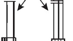
Contact block/pad. This simple design (Figure 1) suits all surfaces and provides good immunity to the ambient environment. The sensing element is built into a brass, copper or stainless steel pad that is fastened to the surface by bolts/screws, clamps or welds. Mounting blocks come in a variety of shapes to fit different surface profiles — flat, V-block, radius and custom. The sensing element can be a 2- or 4-wire RTD or a thermocouple. The design can handle harsh conditions, e.g., high temperatures, high humidity or dirt; temperatures can range from 0° to 200°C (32° to 392°F) with conventional cable and from -196° to 600°C (-320° to 1,112°F) with MI cable, depending on the sensor type used.
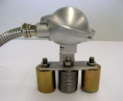
Magnetic mount. In this design one or more magnets hold the tip of a spring-loaded thermocouple sensor tightly against a steel or other ferromagnetic surface (Figure 2). It suits surfaces of varying shapes (flat, curved or irregular) and temperatures from –50° to 150°C (-58° to 302°F). Because the unit can be moved, it's useful for applications such as hot spot detection.
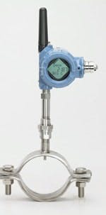
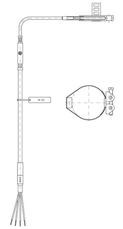
Metal contact block design and worm-drive hose clamp. This design (Figure 4) is a good solution for round surfaces. It can handle harsh environments with high temperatures, high humidity and dirt. Equipped with an RTD or thermocouple, it can be used at temperatures from –196°C to 600°C (-321° to 1,112°F). The contact block usually is stainless steel or copper.
APPLICATION EXAMPLES
Surface temperature sensors already have proven themselves in a variety of plant duties, including:
Reactor surface temperature measurement. This application involves a gasification reactor. The unit operates at high temperature; it's very important to detect any damage to the expensive and fragile refractory lining because damaged refractory can lead to a complete reactor failure. Refractory damage causes hot spots on the outside surface of the reactor that waste energy but also warn of possible future failure. The problem is to detect these hot spots.
The solution was a magnetic mount sensor that could be moved from place to place to check suspicious spots. The sensor has a single 3-mm Type K thermocouple and is connected via 10,000 mm of armored cable.
This sensor has enabled early detection of hot spots and reduced both operating and maintenance expenses.
Conventional measurement using surface sensors with strap-on clamps didn't provide the needed accuracy and was slow to respond to temperature changes. It was tough to maintain the proper temperature without over- and undershoot. In addition, the sensors were difficult and time-consuming to replace, which increased the risk of product loss or a process shutdown if a sensor failed.
The answer was to use pipe clamp sensors with RTD elements and spring-loaded silver tips for good thermal contact and fast response. These are connected to high density temperature transmitters, each with eight inputs. Installation was both easy and cost effective; the sensors provide the needed measurements more reliably and accurately than the conventional method. In addition, the sensors' replaceable measuring inserts help ensure process integrity.
High pressure steam boiler surface temperature monitoring. Measurement was a challenge because of very high mechanical vibration levels, high density measurements with longer length cables, an operating temperature of 600°C (1,112°F), a total temperature range of 0° to 800°C (32° to 1,472°F), and the need for metal-to-metal contact on boiler tubes.
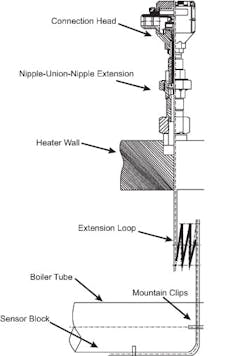
The sensor used is a stainless steel contact block design equipped with a 3.2-mm Type K thermocouple. This is mounted with clips to a boiler tube (Figure 5); a MI expansion loop handles issues of expansion and contraction without damaging the sensor. The sensors are connected to a high density temperature transmitter.
Benefits include accurate boiler fatigue calculation, early detection of boiler tube failures and hot spots, reduced boiler operating and maintenance costs, increased sensor life under harsh conditions and lower cabling costs.
GUIDELINES FOR NON-INTRUSIVE MEASUREMENT
Several simple precautions can help ensure the best accuracy with surface temperature measurement. First, confirm the temperature being measured is actually that of the surface of the vessel or pipe by minimizing the effects of the surroundings — by making certain that thermal contact between the sensor and the surface is good and stays that way over time. Choose a sensor body material that's compatible with the surface to be measured and won't cause galvanic action that'll build up a layer of corrosion, increasing thermal resistance. For magnetic mount sensors it's a good idea to minimize the actual area of contact between the sensor tip and the surface.
For welded sensors differential expansion can pose the biggest challenge. Large differences between the expansion coefficients of the sensor contact block and the surface can cause severe stresses. Where large temperature changes occur over time — as, for example, during startup of a furnace — these stresses (perhaps aggravated by vibration) actually can tear the sensor off the surface.
DANJIN ZULIC is a marketing engineer, global temperature marketing, for Rosemount, Emerson Process Management, Chanhassen, Minn. E-mail him at [email protected].
