Mastering Gas Chromatography: Unlocking Efficiency with Sample Conditioning and System Design
In This Article
- Understanding the Sample Port
- Sample Conditioning’s Role in GC Optimization
- Columns, Sample Valves, Controllers and Shelters
- Selecting a Detector
-
- Flame Ionization Detectors
- Thermal Conductivity Detectors
-
- Other Things to Consider
-
- Peak Issues
- Data Communication
- Ancillary Systems
-
In the online analyzer jargon, gas chromatograph (GC) systems are considered “extractive,” in the sense that a representative sample is drawn, or extracted, from the process stream, processed using sample conditioning to make it suitable for the GC. From there, you can perform GC analysis, make process adjustments if used in the process control and report the results.
Figure 1 shows a typical extractive GC system with its major subsystems including sample port, sample conditioning, carrier gas, GC sample valve/switching valve, GC column and controls, sample return/disposal and data management. Depending on the application, a GC system is suitable for either a single sample analysis or sequential analysis of multiple samples. They may be housed in a building/shelter or in a shade.
The core function of any GC system is to provide accurate sample analyses with good precision in the shortest practical time. GC analyzers have a wide range of applicability in terms of the number of chemicals and their composition, from ppm to percent level.
Unsurprisingly, GC systems are not immune to problems. Although GC system problems can originate from myriad sources, a system view helps us formulate an effective strategy for anticipating and avoiding potential problems.
Understanding the Sample Port
- Don’t design a sample port on control valve bypass, drains or vents, level bridle and other dead spots. If the sample port needs to be installed on a large vessel or a reactor, make sure the area near the sample probe is well-mixed.
- Flow obstructions such as ells, reducers, trees, control valves, block valves, thermowells or orifice plates or pitot tubes cause flow disturbances, which could cause sample distortion. Typically, sample probes require 10 pipe diameters of straight, unobstructed pipe upstream and five diameters downstream, though exact requirements vary with flow characteristics and obstruction type. When extracting a sample from a vessel, tank or reactor, make sure the sample pot is in a well-agitated zone.
- Probes protruding in the pipe are preferable to probes that are flush with the pipe wall. This is particularly important if the process stream is laminar with static film. In large pipes with high turbulent flows, ensure the sample probe has sufficient mechanical support.
- The probe opening should face the flow. Avoid sample probes entering from the bottom of a horizontal pipe or vertical pipe with downward flow.
- While stainless-steel probes are common in many applications, highly corrosive processes may require exotic metallurgies. Consider not only the main constituents of the sample, but low-level, highly corrosive impurities as well to ensure that the probe will not be affected by corrosion. As a quick guide, probe metallurgy should match with that of the process vessels or piping.
- For pipeline sample ports, avoid bottom entry for a horizontal pipe. Avoid sample ports on a vertical line with downward flow. For vapor samples, if you anticipate significant liquid entrainment, you may need to consider deflectors or chevron separators to remove liquid.
- Provide for safe isolation of the process from the sample system. For processes at very high pressures, consider double block-and-bleed arrangement. Similarly, for extreme temperatures, consider appropriate insulation.
Sample Conditioning’s Role in GC Optimization
- Remove liquid droplets and or particulates if they are not a part of the analytical requirements. However, if droplets and/or particulates are a part of the analytical requirements, then liquid will need to be vaporized. Heavy molecular liquids and particulates are not suitable for GC analysis, and they will need to be analyzed by different techniques such as liquid chromatography.
- Fine filters, say 1 to 2 microns, can be used to remove particulates. In cases where the proportion of undesirable particulate entrainment increases, you will need consider strainers to remove some particulates before sending the sample to the fine micron filters.
- Most GCs operate at 20 psig to 30 psig. For high-pressure processes, use pressure regulators (reducers) with appropriate safety systems. Also, provide block valves with a tight shutoff to isolate the process from the sample system.
- If the process involves chemicals, such as light hydrocarbons, that could undergo Joule-Thompson cooling effect, ensure you have adequate heating or temperature-controlled heat tracing to prevent condensation. Effective steam trace requires no accumulation of the condensate in the line. Electric heating should make close contact with the sample line.
- A pressure booster/blower must be provided for processes at low pressure or vacuum. With vacuum systems, you need to consider the possibility of air ingress.
- Electrical-area classification requirements may force the GC systems or their shelters to be installed in non-rated areas, which could be far from the process. This will, in turn, increase the time lag in reaching the GC. Fast-loop arrangements may be required in some situations. In a fast-loop arrangement, a slip stream from the process is routed closer to the GC, where a sample is withdrawn. This, in effect, reduces the time lag between the process and the analyzer.
- Obviously, carrier gas supplied from gas cylinders must be maintained at a set pressure and flow rate with a specified purity level. Excessive moisture or impurities will affect GC reliability and expected useful life. When the gas cylinder needs to be switched, be aware of the need to purge air pockets, which if left in the sample line, could cause nuisance peaks.
Columns, Sample Valves, Controllers and Shelters
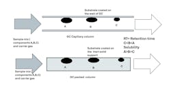
- GC column length depends on the granularity of analyses. As you increase the number of components for detection, column length increases.
- Poor temperature control of the GC oven could cause a shift in retention time and result in erroneous analyses reported by the system.
- With use and depending on your application, a GC column could accumulate heavy chemical species, which could result in ghost peaks.
Selecting a Detector
- Make sure all functional requirements for proper functioning of the detector are met. For instance, hydrogen/air used for FID must have the required purity, pressure and flow rate. Since thermal conductivity (T/C) of a gas is influenced by temperature, it is important to ensure that the T/C has set temperature.
- Periodic maintenance of the detector and ancillary equipment are vital for high reliability.
- During the selection and operation of detectors, pay attention to potential interference by impurities. The concentration of chemical species of interest and linearity of response also determine the type of detector suitable for your application. For example, electron capture detectors would be preferable to FID for determining concentration of chemicals in the ppb (parts per billion) range.
- Provide for safe venting/disposal of gas stream after it comes out of the detector chamber. Gas venting must be in a safe location, away from congested areas. If the gas is vented to a flare header, provide a check valve on the sample exhaust to prevent contamination from backflow.
- Diagnostics, relevant coded messages and settings are often vendor specific and equipment manual should be consulted.
Flame Ionization Detectors
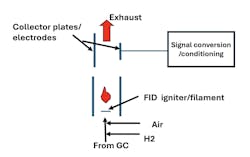
- Make sure hydrogen and air with the required purity, ratio, pressure, temperature and flow are provided to the detector. Follow purity specifications from the vendor. Not meeting these requirements can cause the flame to be unstable or flame may not stay lit.
- At the start up, if the temperature of the igniter (filament) is too low, it will not sustain flame. Typically, the temperature of the filament is kept 40–45 °F above the GC temperature to ensure stable flame during light off of hydrogen. With use, FID detectors would need to be cleaned periodically.
- Gas coming out of an FID should be disposed of at a safe location. In addition, hydrogen is a highly flammable gas; good ventilation and air monitoring is vitally important. Similarly, during maintenance/troubleshooting an FID, keep in mind the igniter may be hot to the touch and consider hydrogen flow a part of safety precautions.
Thermal Conductivity Detectors
- Make sure there is unimpeded and leak-free flow of gas from the GC, reference gas with the required purity, pressure and flow and electrical connections secure with proper polarity. Obviously, lack of adequate purity could affect baseline, analysis and could even damage the resistor (filament).
- Although helium (He) is the preferred carrier gas, supply shortages may require you to change to another gas, say hydrogen or nitrogen. Because of significantly higher thermal conductivity of He relative to other chemical compounds, it gives excellent sensitivity in detecting chemical constituents.
- Corrosive or fouling species will tend to destroy resistors. Baking the TC should help remove the fouling deposits. If that fails, the resistors will need to be replaced.
Key Takeaways
- Effective Sample Conditioning: Proper sample conditioning is essential for accurate gas chromatography (GC) analysis. Removing particulates, ensuring consistent temperature and pressure, and minimizing system delays improve reliability.
- GC System Design: The overall GC system, from sample port to detector selection, requires careful design and maintenance to avoid issues like flow disturbances, ghost peaks, or contamination.
- Troubleshooting: Anticipating and diagnosing potential issues — like baseline noise or sample distortion — requires a system-wide approach, including network considerations and consistent maintenance of ancillary components.
Other Things to Consider
Peak Issues
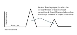
- Baseline noise or spikes can be caused by several sources, including electrical sources, such as loose connections or improper ground or mechanical sources, such as leaks in rotary valves. As noted earlier, fouling in the GC column could also cause spikes or ghost peaks.
- Excessive sample volume can cause the peaks to distort. Similarly, impurities could also distort signal peaks. Impurities in the sample or carrier gas can cause ghost peaks. When you need to switch carrier gas cylinders, trapped air causes nuisance peaks for a short time.
Data Communication
- If you are adding one or more GCs to existing bank of GCs, be aware of the network capacity (number of nodes) of the existing network (say, Modbus). Network capacity limitation is, however, an uncommon issue.
- System configuration and wiring requires careful attention to each point of the GC system. Just as in electrical systems, problems crop up because of loose wires, missing or wrong point-to-point terminations, unshielded wires (e.g., EMI problems), wires too close in the cable tray, water /snow/dirt ingress and improper grounding and lack of voltage regulation. Use of fiber optics may merit consideration if there is a high potential for EMI issues.
- Anticipate cybersecurity concerns with connecting to the internet. Safeguards, such as access control, firewalls and intrusion-detection systems, along with patch management and disaster recovery guidelines are crucial.
Ancillary Systems
- Set up a detailed maintenance/inspection and calibration schedule including daily, weekly, monthly or semi-annual checkups and repairs. Provide relevant spare parts. In many operations, timely availability of analyses may be critically important.
- Keep updated documentation/drawings of the system for training and streamlining the troubleshooting process. Keep all relevant stakeholders updated.
References
- Rosemount-Emerson, “Application Note-Fundamentals of Gas Chromatography,” Emerson Automation Solutions, www.emerson.com/documents/automation/application-note-fundamentals-of-gas-chromatography-rosemount-en-105270.pdf
- Hoffman, Michael (Siemens Industries); “Make your process analyzer smarter,” Chemical Processing, May 2014, Putman, www.chemicalprocessing.com/automation/automation-it/article/11337155/instrumentation-make-your-process-analyzer-smarter-chemical-processing


