THIS MONTH'S PUZZLER
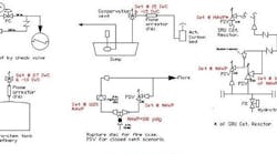
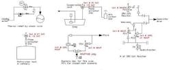
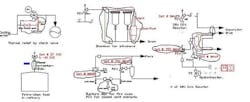
A safety expert from headquarters surveyed our refinery's pressure relief system and took issue with a number of practices, including use of a check valve for thermal relief, connecting blowdown lines to the discharge of a pressure safety valve, and having several relief devices share a common discharge (Figure 1). Operations dismiss the expert's comments as quibbling to justify the survey and maintain nothing is wrong with the current solutions to these pressure relief problems. Please help me convince them these really are problems.
THE PROBLEMS ARE REAL!
Let's address each specific concern, starting with the check valve used for thermal relief. Check valves are notorious for leaking. In this case, you have process pressure against the "flap" of the check valve if it is mounted to open in the direction of flow. Depending on the spring loading, the check valve is leaking water continually. If there is a heat exchanger leak, you could have an air permit violation. You need a pressure safety valve (PSV).
Connecting blowdown lines to the discharge of a PSV is borrowing trouble. Material will accumulate at the downstream side of the PSV. The relieving capacity of the PSV will be reduced, possibly to a point where it can no longer protect the equipment it was designed to protect. The inlet upward force from the relieving pressure has to overcome the downward force — the PSV spring force and the backpressure — to lift. If material accumulates in the header, you have increased the downward acting force to a point where you have compromised the mechanical integrity of the vessel being protected. A process hazard analysis (PHA) or layer of protection analysis (LOPA) should have captured this problem, requiring the routing of the blowdown streams away from the PSV discharge.
Having several relief devices share a common discharge is a similar problem. When relief valve (RV) discharge lines are common, the designer must account for the combined relieving flow from each RV and its impact on other valves. You have effectively increased each RV's amount of built-up backpressure, the pressure created by other flows in the network, which could impact its relieving capacities. Backpressure is built-up and super-imposed. Normally 10% is allowed for overpressure; RV flow is at set pressure plus overpressure. Fire case sizing allows 21%. For a conventional RV, the backpressure cannot exceed 10% of the set pressure of the RV or the flow capacity will be reduced. If, by combining the flows for each RV, the backpressure exceeds 10% in the vent the capacity of those RVs will be reduced and the mechanical integrity of vessels will be compromised. I would suggest revisiting the PHA/LOPA for these designs and I would also have the safety expert participate in the discussions.
Eric Roy, principal engineer
Westlake Chemical, Lake Charles, La.
CAREFULLY CONSIDER BACKPRESSURE
The operations personnel who do not accept the expert's comments as valid should thoroughly read API Recommended Practices — API RP 520 and 521 — and other relevant international guidelines. In general, referring to all the examples, it should be highlighted that the performance of a relief device significantly depends on the backpressure that occurs during the relief scenario. API RP 521 requires that backpressure for a conventional PSV be limited to 10% of the set pressure. A balanced PSV, such as a pilot-operated valve, can take a higher backpressure. Backpressures on each relief device in the refinery should be evaluated with peak relieving flow rate for a conservative and credible concurrent relieving scenario such as emergency shutdown at maximum operating, trip pressures or PSV set pressures. Higher flow rates at the discharge would also mean higher fluid velocities in the PSV tailpipes, which could lead to acoustic-induced vibrations and flow-induced vibrations. Sonic velocities in the PSV tail pipes can cause fatigue failure damage depending on the type of stresses. These calculations can be done with the aid of software. Let's consider the thermal relief case. A check valve may not be acceptable as thermal relief depending on the service (e.g., flashing liquid). A smaller size relief valve such as ¾ in. × 1 in. is often installed for thermal relief.
Nikhil Barbare, senior process engineer
Transfield Worley, Perth, Australia
ADHERE TO CODES
Let's start from upper left to right of Figure 1. Check valves are no substitute for relief devices or as inlet or outlet valves. API RP 520, Part II, 5th edition, Section 6.3.1, states: "Valves shall have the capability of being locked or car sealed open." Obviously, check valves don't qualify. Replace the check valve with a PSV set to the maximum allowable working pressure of the heat exchanger. In the second case, isolate the PSV discharge from the blowdowns with a tank (Figure 2).
Connecting one or more relief devices to a common discharge though ubiquitous is often wrong; different corrosion requirements and handling a refinery-wide fire make this a bad idea. Common headers are okay if the manifold is large or the PSVs are pilot or bellows, which allow greater backpressure — but only if a complete scenario study is conducted. Another issue is reliability: pilot PSVs are complicated. Remove the check valves; consider isolation rupture disks (PSEs) for corrosion isolation.
While API 520 Section 6 allows an inlet automatic valve, bleed valves must be installed between the inlet and relief device to test for leaks, the same as for a PSE/PSV combination. A pressure gauge or switch is required here; use a switch for inaccessible applications.
The combination of a PSE and a smaller PSV addresses two different scenarios. Clearly the PSE is for a less frequent event, probably a fire, and should have the higher setting; the relief valve is probably for a blocked valve scenario. The PSV should be set to a lower pressure, as allowed by ASME code but not greater than 80% of the disk burst pressure; check with the disk vendor. A blocked valve could be from a feed pump or liquid expansion from a reboiler, not vapor, so an isolation pot is required for the PSV discharge.
Now, consider the globe valve below the PSE. According to API RP 520, Part II, Section 6.3.1, "valves shall be full bore." ASME Section VIII requires that the opening through all pipe and fittings between a pressure vessel and its pressure relief valve shall have the area of the pressure-relief-device inlet. I doubt if a 4-in. globe valve meets this requirement.
Last, consider the storage tank in the left-hand corner. Flame arrestors are not required if they will impede flow. API-2000 Section 4.4.1.2 states, "A flame arrestor is not considered necessary in conjunction with a PV valve venting to the atmosphere because flame speeds are less than vapor velocities across the seats of PV valves." Remove the flame arrestor immediately. There are two other relief issues that require attention: 1) only a floating head tank does not require an emergency vent (fire); and 2) fume control, e.g., an activated carbon bed, is usually required to catch benzene and other carcinogens.
Dirk Willard, process engineer
Fluor Global Services, Inver Grove Heights, Minn.
JUNE'S PUZZLER
Our liquid ring vacuum pump repeatedly tripped during high pressure, high flow conditions at startup. When it finally started, the pump ran noisily. On inspection, we noticed it was installed backwards. We reversed the direction of the pump but got only low vacuum and the motor became very hot — exceeding the temperature ratings on the motor insulation. We're operating at 300 torr with water. Why did the pump operate, though noisily, with the flow reversed? What is causing it to run so poorly now? Is the pump shot?
Send us your comments, suggestions or solutions for this question by May 11, 2012. We'll include as many of them as possible in the June 2012 issue and all on ChemicalProcessing.com. Send visuals — a sketch is fine. E-mail us at [email protected] or mail to Process Puzzler, Chemical Processing, 555 W. Pierce Road, Suite 301, Itasca, IL 60143. Fax: (630) 467-1120. Please include your name, title, location and company affiliation in the response.
And, of course, if you have a process problem you'd like to pose to our readers, send it along and we'll be pleased to consider it for publication.


