Quest For Clean Air: Thermal or Catalytic?
Concern over the effects of air pollution on the environment is not new. However, increased public awareness of U.S. Environmental Protection Agency (EPA) regulations regarding harmful air emissions such as volatile organic compounds (VOCs) and/or hazardous air pollutants (HAPs), along with an industry-wide long-term commitment to comply, have sharpened the focus on control-technology developments. To meet stringent local, state and federal clean air requirements, companies in a wide variety of industries are installing new emission control systems or replacing existing technology with more modern and efficient equipment. With more than 25 years of proven success, both catalytic and thermal oxidation technologies represent effective methods for controlling VOC and/or HAP emissions.
Catalytic and thermal oxidation systems destroy the harmful VOCs and HAPs emitted by processing operations by collecting the emissions and destroying them using high temperatures and/or an industrial-grade catalyst. Both catalytic and thermal oxidation ensure thorough VOC and/or HAP destruction. Today's modern and efficient systems use high-efficiency heat exchangers, natural-gas-fired burners, industrial-grade blowers, electric or pneumatic actuators and programmable logic controllers (PLCs) to ensure safe, efficient operation.
Regenerative Thermal Oxidizers
Thermal oxidization promotes a chemical reaction of the VOCs/HAPs with oxygen at elevated temperatures. This reaction destroys the pollutants in the air stream by converting them into carbon dioxide (CO2), water and heat. Three interdependent and critical factors -- time, temperature and turbulence -- control the rate of reaction.
Process exhaust fumes are forced into the RTO inlet manifold (with a high-pressure supply fan) and directed into one of the energy-recovery canisters via inlet control (switching) valves. The VOC/HAP-laden air passes from the valve assembly vertically upward through the first of the two heat-exchanger canisters, where it adsorbs heat from the ceramic media, eventually cooling the media.
This preheated air then enters the combustion chamber, typically at a temperature very close to that required for oxidation. It is mixed thoroughly for temperature uniformity and held in the combustion chamber at elevated temperatures from 1,500°F to 1,800°F for a residence time between 0.3 second (sec.) and 1.0 sec.
VOC/HAP destruction takes place within the combustion chamber; auxiliary fuel is introduced if necessary.
After passing through the combustion chamber, the hot, clean air is routed vertically downward through the second energy-recovery canister, where the ceramic media adsorb the heat generated during thermal oxidation and preheat the media for the next cycle. The cooled, clean air is routed to the atmosphere through outlet control (switching) valves, the exhaust manifold and, ultimately, through the exhaust stack. To maximize the heat exchange, the switching valves alternate the airflow path between the canisters to regenerate continuously the heat stored within the ceramic media. Thermal efficiency ranges from 85 percent to 95 percent. To maintain low external shell temperatures and minimize radiant heat loss, the combustion chamber is insulated with long-life ceramic fiber modules.
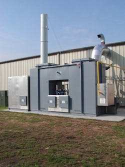
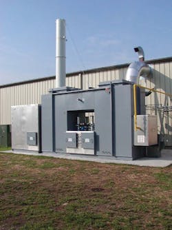
Figure 1. Bring on the Heat
RTOs use very high temperatures to promote a chemical reaction of the VOCs/HAPs with oxygen, offering a destruction efficiency of more than 98 percent.
Catalytic oxidizers
Catalytic oxidation uses an industrial-grade catalyst to promote the chemical reaction at lower temperatures than those required for thermal oxidation. The VOCs/HAPs still are mixed with oxygen and heated to an elevated temperature, destroying the pollutants in the air stream by converting them to CO2, water and heat. The reaction rate is controlled by the temperature in the catalyst chamber and the amount of time the pollutants spend within the catalyst. Catalytic oxidizers usually require less energy to operate than do thermal oxidizers because the technology operates at lower temperatures.
Process exhaust fumes are forced into the catalytic oxidizer inlet plenum (using a high-pressure supply fan) and directed through the "cold" side of a high-efficiency counter-flow plate-type heat exchanger. The VOC/HAP-laden air then enters the combustion chamber, typically at a temperature very close to that required for oxidation. It then is mixed thoroughly for temperature uniformity.
To maintain a set-point temperature, auxiliary fuel is introduced if necessary.
The 500°F-to-650°F preheated stream then passes through a fixed bed of industrial-grade catalyst, where VOC/HAP destruction takes place.
After passing through the catalyst chamber, the hot, clean air is routed back through the "hot" side of the heat exchanger, where it preheats the incoming process air continuously. After exiting the heat exchanger, the cooled, clean air is routed to the atmosphere through an exhaust chamber and, ultimately, through the exhaust stack. Heat exchangers in standard catalytic units are typically fabricated from heavy-duty stainless steel. Thermal efficiencies range from 50 percent to 80 percent. Internal chambers of a catalytic oxidizer are manufactured entirely of heavy-gauge stainless steel. Thermal expansion joints are incorporated where necessary. To maintain low external shell temperatures and minimize radiant heat loss, the internal chambers are covered with blanket insulation and then are clad with aluminum sheeting or another suitable material.
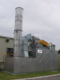
Figure 2. Catalytic Conversion
Catalytic oxidizers operate at lower temperatures than RTOs, typically resulting in lower energy requirements, and provide a VOC/HAP destruction efficiency of more than 98 percent.
System selection
On the other hand, very high VOC/HAP concentrations would completely rule out the use of some technologies such as RTOs or regenerative catalytic oxidizers with high-efficiency heat-recovery systems. Low concentrations of VOCs/HAPs would clearly favor the regenerative technologies.
You should also consider space requirements and installation locations. The technology selection criteria should not be influenced heavily by the equipment floor plan. Air pollution control systems typically are installed outdoors and can be placed on the ground, on the building roof and/or on an elevated structural steel platform.
Depending on your process airflow requirements, systems will range from 8-feet (ft) wide by 20-ft long and 8,000 pounds (lb) to more than 40-ft wide by 60-ft long and 180,000 lb. You first should become comfortable with the technology selection from an operational point of view and then consider space requirements.
When selecting and/or sizing an air pollution control system, consider your facility's growth expectations during the next two to five years. List the total number of both present and future emission points (exhaust stacks) to be controlled. The system's electrical control design could change, depending on the number of emission points. Also take into account the system's expected hours of operation. It typically is less costly to install a system designed to handle additional capacity now instead of retrofitting it later or installing a second system in the near future. Also, many equipment vendors can provide/install their systems under a turnkey contract that makes the vendor responsible for all aspects of both installation and startup.
As the cost of energy in North America continues to rise, purchasers should consider options to use the heat energy emitted to atmosphere. Depending on the VOC/HAP abatement technology being used, exhaust stack temperatures vary between 150°F and 700°F. You can recover this heat energy and return it back to the facility for use in process heating hot-oil or water coils, low-pressure steam production, comfort-heating systems or a combination of these uses.
Maintenance costs have been reduced drastically over the years as air pollution control systems supplied by reputable vendors have become very reliable. However, long-term repair costs might vary greatly between different technologies if a major failure related to the airflow-switching valves, the media support structure in a RTO or the catalyst in a catalytic oxidizer were to occur. To ensure proper long-term operation and to reduce the risk of major repairs, you should implement and adhere to a stringent preventive maintenance program. You could arrange for in-house maintenance personnel to be trained to support preventive maintenance checks, or you could purchase an annual preventive maintenance program from an air pollution control system vendor.
Work with the vendor
In some cases, a prepackaged system might suffice; however, a company often can get an enhanced system by seeking a customized solution. Many vendors offer tailored solutions at no additional cost, so you should take advantage of this opportunity and purchase a system built to meet your individual requirements. A system designed specifically for the customer's site will offer more options for installation locations, will potentially cost less to install and ultimately will require less space.
Consider asking the vendor to provide name-brand components such as fans, motors, burners/fuel trains, variable-frequency drives and more that might already be widely used in the facility. These components should not cost extra but could reduce the different types of spare parts needed in stock.
Because of differences in terminology and component quality, it can be difficult to understand and evaluate the differences between one air pollution control system manufacturer's offerings and another's. The more thorough and precise you can be in providing operating and design criteria, the more likely your project will result in a system that meets your company's specific needs and provide years of trouble-free service.
Martinson is president of The CMM Group LLC, De Pere, Wis., which manufactures custom-designed air pollution control systems and provides emergency field service, preventive maintenance programs, engineering services, system retrofits and rebuilds, turnkey installation and spare parts for all makes and models. Contact him at (920) 336-9800.


