Condensate often gets overlooked and ignored. Often thought of as an inexpensive byproduct, condensate can allow you to conserve make-up water and save on expensive treatment chemicals.
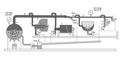
Condensate is a ready-made supply of recoverable energy for a boiler system (Figure 1). Chemical plants typically should be able to recover more than 60% of the generated condensate. However, traditional system designs and installation practices often can't ensure positive condensate drainage. As a result, the condensate frequently is drained to waste when the heat exchanger stalls, diminishing performance.
Making simple changes in system designs and following practical management steps can return significant savings as well as increase heat exchanger performance and integrity.
DRAINAGE DESIGNS
Return of condensate to the boiler plant requires some means of motive pressure. This comes from the supply steam pressure or via a mechanical pump. Either way, the motive pressure always must exceed the condensate return backpressure to guarantee continuous drainage.
Two common piping designs for heat-exchanger condensate drainage are to incorporate a level-actuated collection pot or use steam traps. Both types of devices are direct piped to the condensate return system and can be affected by varying return line backpressure.
A level-actuated collection pot often is chosen for large, high-capacity high-pressure reboilers as well as vacuum columns and flash tanks. The heat-exchanger control scheme can be a constant-level design incorporating a modulating steam valve for temperature control, or a variable system employing a constant-pressure steam supply while changing the exposed heat-exchanger surface area. Both approaches use an actuated drain valve to maintain condensate levels.
Both designs provide process temperature control but pose potential performance and equipment-integrity problems.
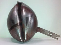
The constant-level control system relies on varying steam pressure and volume to maintain desired process temperature. As the thermal requirement decreases, the modulating supply-steam control valve closes, reducing steam pressure and volume. This results in low condensate return motive pressure. If the steam pressure in the heat exchanger becomes less than the condensate backpressure, a flooded condition will arise -- decreasing thermal performance, creating a corrosive condition (carbonic acid from cooled condensate), spurring surface pitting (accelerated by trapped noncondensable gases) and potentially compromising the structural integrity of the tubes, tube sheets and other components through stress cracking and water hammer (Figure 2).
The variable-level control system relies on constant steam pressure -- the condensate drain valve is modulated to expose or flood the heat exchanger surface area. As thermal requirements decrease, the condensate drain valve closes to back up condensate into the vessel, effectively reducing the surface area exposed for heat transfer. The constant steam pressure provides a positive motive pressure for condensate return. Again, though, the downside is corrosion and decreased vessel life and structural integrity.
A steam trap is designed to drain condensate and vent noncondensable gases without allowing live steam to escape. Because its internal mechanism performs as a discharge control valve, the steam trap inherently operates comparably to a constant-level condensate system.
Similarly, with adequate steam pressure to overcome the condensate return backpressure, the heat exchanger will perform with optimum efficiency -- and if the supply-steam control valve closes due to reduced thermal requirements, the available condensate motive pressure decreases and potentially backs up and floods the vessel. Again, the heat exchanger loses performance and becomes subject to corrosion and structural damage.
Optimize Your Steam System, Part 1 -- Maintaining an efficient and reliable steam system is very critical for the plant's process integrity and financial health.
Optimize Your Steam System, Part 2 -- A simple four-step process can improve steam efficiency.
The recurring theme is that positive pressure is required to ensure condensate drainage and non-condensable gas venting from heat exchangers. Unfortunately, the quick remedy to drain a flooded vessel is to open valves to the atmosphere, wasting valuable energy and creating a potential safety hazard.
Incorporating a pumping device will prevent heat exchanger flooding and ensure positive motive pressure to overcome any backpressure in the condensate return, keeping the heat exchanger operating at optimal efficiency and assuring structural integrity.
EQUIPMENT STALL
Stall is a condition in which heat transfer equipment can't drain condensate and becomes flooded due to insufficient system pressure.
Stall occurs primarily where the steam pressure is modulated to obtain a desired output (i.e., product temperature). The control requirements for heat exchangers (coils, shell-and-tube, etc.) can be segmented into two distinct modes: optimal performance and stall.
During optimal performance, the exchanger's operating steam pressure exceeds the backpressure present at the discharge of the steam trap. Therefore, a positive pressure differential exists across the trap, allowing for condensate to flow from the heat exchanger to the condensate return line.
In the stall mode, the exchanger's operating pressure is less than or equal to the backpressure present at the discharge of the steam trap. As a result, no pressure differential exists to force the condensate through the steam trap. Condensate begins to collect and flood the heat exchanger.
When exchangers become flooded due to stall, a variety of problems -- including water hammer, frozen coils, corrosion, poor temperature control, short equipment life, control valve hunting (system cycling) and reduced heat transfer -- can occur. Hammer and corrosion can lead to damage to the tube bundles/coils, causing product to contaminate the condensate; this also can create serious problems at the boiler.
Installing a mechanical pump in a closed-loop arrangement allows maintaining a dry heat exchanger regardless of the steam-system pressure, condensate rate or efficiency of the tube bundle. This eliminates tube bundle corrosion and potential tube failure; both could cause an upset condition and interrupt production. By ensuring condensate removal, you can take advantage of all the surface area available in the tube bundle. The heat exchanger can operate at the optimal performance level while utilizing the lowest, most-efficient steam pressure required.
In new construction putting a mechanical pump on process heat exchangers can lead to savings on installation costs. For vacuum systems, net positive suction head is critical for typical electric pumps. Therefore, heat exchangers often are elevated to extreme heights to allow for proper drainage. Because they are immune to the cavitation issues that cause failures in electric pumps, mechanical pumps can reduce the skirt height required for columns or reboilers, which often can lead to thousands of dollars in construction savings.
CONSIDER THE BIG PICTURE
Condensate management requires a holistic approach to realize significant energy savings. Here're a few practical points to remember:
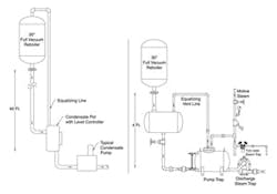
From a design perspective, gravity and distance play key roles in efficient recovery and return of condensate to the boiler. A typical system design involves overhead condensate return lines as well as long piping runs. Vacuum systems may require extensive elevations to drain a conventional level-control condensate pot.
Adding a device such as a pumping trap can minimize the height necessary -- sometimes to as little as four feet -- which can lead to savings of thousands of dollars in construction costs alone (Figure 3). A pumping trap also enables the heat exchanger to run at its lowest, most-efficient steam pressure, minimizing energy consumption.
The sizing of condensate return piping is another critical design factor. Lines must be large enough to accommodate the movement of liquid condensate as well as the presence of steam and flash vapor. In addition, receivers (flash tanks in open/vented system) must be sized to provide adequate separation of flash steam and condensate; failure to properly size receivers may cause upset conditions within the drainage system. Vent lines also must be sized adequately to decrease flash steam velocity, which likely will reduce the risk of condensate carryover.
A properly sized steam trap also is essential for efficient system operation. A number of variables dictate which type of trap to use but, in general, mechanical inverted-bucket traps usually prove to be the best solution because they allow continuous drainage of condensate. A rule of thumb is to locate traps at 100–300-ft intervals.
Condensate collection assemblies, which bring multiple valves together in one central location, may offer advantages by reducing the number of individual condensate collection points along a line -- cutting installation costs and space requirements and increasing accessibility to equipment for routine maintenance and repairs.
Simple management practices such as insulating distribution and condensate return lines can pay big dividends. Insulation can reduce energy losses by 90%; insulate any surface over 120°F. Establishing a routine steam-trap inspection and maintenance program also is essential for maximizing condensate recovery and return. An effective trap management program alone can achieve fuel savings of up to 10%.
STEVE ASHBY is sales manager, Condensate Management Group, for Armstrong International, Three Rivers, Mich. E-mail him at [email protected].
