Look Beyond Orifice Plates
Dec. 29, 2008
Related Content
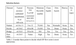
Flow meters based on differential pressure (DP) represent a popular choice in the chemical processing industries — in fact, they account for a large plurality of installations. DP meters are used for liquid, gas and steam metering in both normal and extreme high temperatures and pressures.All DP primary elements restrict the flow in some way. A restriction in a pipe results in an increase in the fluid velocity, according to Bernoulli’s law of conservation of energy. The ensuing conversion to kinetic energy reduces the static pressure. This pressure drop, the measured DP, is proportional to the square root of the flow rate and thus provides a means to measure flow.The elements have no moving parts and can be fabricated in a wide selection of materials. Their purchase price is relatively low, even for large pipe sizes. Accuracy is moderate, ranging from 1% to 5%; compensation techniques can improve these values to better than 1%. Extensive research over decades has led to optimization of the flow elements and development of standards. DP meters are generally easy to select for a specific application.Disadvantages revolve around rangeability, installation costs, density and flow profiles. The square-root relationship limits the range of flow rates that realistically can be measured in a particular application; the typical rangeability is 4:1 or slightly higher. Installation requires a DP transmitter, manifold, valving and impulse lines. The impulse lines leading to the DP transmitter can become plugged unless remote seals and filled capillaries transfer the pressures to the transmitter. The measured value varies with fluid density for both volumetric and mass flow. Additionally, flow elements tend to be sensitive to flow profiles within the pipe, requiring long upstream pipe runs or flow-straightening devices. While the orifice is the most common restriction associated with DP measurement, several others — venturi tubes, flow nozzles, wedges and flow tubes — have found a solid place in process applications. Users should look at these designs, too, to come up with the optimum DP meter for the particular operating conditions and requirements. An important consideration is the pressure drop, which as a rule of thumb should be as small as possible. Technologies such as venturi tubes, flow nozzles, wedges and flow tubes feature very small pressure drops, leading to reduced energy loss and pumping requirements. So, in this article, we’ll look more closely at these elements.Figure 1. Classic Venturi Tube -- The outlet cone
gradually diverges, permitting recovery of nearly
all the initial pressure loss.
The classic venturi tube (Figure 1) is a robust flow element that’s useful for applications requiring low loss of line pressure. A venturi tube essentially is a section of pipe with a converging conical entrance (about 20°), a straight cylindrical throat section and a diverging conical exit with a smooth, gradually increasing (about 7°) diameter. Unlike the orifice, the interior surfaces always remain in contact with the fluid. Additionally, because dirt won’t build up as it passes through the contoured sections (as it does in the front of an orifice), this differential producer can serve in dirty flow applications. For the same differential pressure, the classic venturi can pass about 60% more flow than an orifice plate. Years of test data have documented and validated the flow coefficients for various sizes and fluids. Four or more high pressure taps in an annular chamber leading to the straight throat section average the lower pressure reading. Initially designed for large line size (>6 in.) water and wastewater applications, the venturi today ranges in line sizes from 2 in. to 48 in.; installation possibilities include flanged, welded and threaded-end fittings. Manufacturers generally machine the smaller sizes from solid rods, while fabricating the larger sizes from rolled plate. The lengths of the elements typically run five pipe diameters. Because most of the pressure recovers, the venturi is a good choice for large flows where the velocity is higher and Reynolds number, Re, is in the turbulent flow regime. And while it has a relatively long length, the venturi tube requires minimal upstream flow profiling, as its interior shape helps to condition the flow. Rangeability, while better than that of orifice plates, is less than 6:1, with typical accuracies of ±1% to 2% of full scale.Variations of the classic venturi are available. Shorter versions increase the angle of the outlet cone with some sacrifice in pressure recovery. Eccentric inlet and outlet cones can handle mixed phases or build-up of heavy materials. Forms with a rectangular cross-section often serve in ductwork for gaseous flows.Flow nozzles
Like the orifice and venturi tube, these are standard DP elements with extensive generic testing and documentation. Because of their rigidity, flow nozzles are dimensionally more stable at higher temperatures and velocities than an orifice plate. They typically measure fast flows that otherwise might damage an orifice plate from cavitation or erosion. Applications include high velocity steam or fluids with entrained solids. Nozzles aren’t recommended for slurries or dirty fluids that might foul pressure taps. In contrast to an orifice plate, flow nozzles have no sharp edges that might wear over time and degrade performance — so they maintain long term accuracy and offer reduced possibility of distortion. Throat Re should exceed 10,000, although data are available down to about 6,000. The initial cost of a flow nozzle is substantially higher than that of an orifice plate but lower than that of a venturi. However, the permanent pressure loss is significantly greater than that of a venturi. A flow nozzle will pass about 60% more flow than an orifice plate of the same diameter and DP. Because of the nozzle’s streamlined interior, unrecoverable pressure loss is slightly less than that of an orifice but still can range to 40% or more of the DP. The standards for nozzles include ones for the so-called 1932 ISA nozzle, which is uncommon in the U.S., as well as the long radius nozzle.
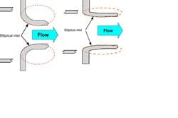
Figure 2. Flow Nozzles -- Low (right drawing) and high
beta ratio long-radius nozzles feature elliptically
shaped inlets.
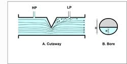
Figure 3. Wedge -- The shape of the restriction allows
solids to pass easily, while its ruggedness resists damage.
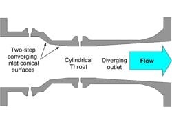
As an example of the wedge meter’s ability to maintain calibration in tough applications, consider two stainless steel meters — one 3-in. and one 4-in. with wafer-type seal connections — that ABB examined after 12 years of service. The meters measured steam-cracked tar, a byproduct of ethylene production. The cracked tar is kept at elevated temperature to prevent solidification of abrasive coke fines and other particles in the process stream. The meters endured temperatures in excess of 355°F and pressures up to 310 psi. Fluid viscosities of 22 cP produced Re of 1,870 and 2,850, respectively, at maximum flow rates. With more than 5 million pounds a month of the abrasive tar being produced, repeatable and reliable measurement was a prime concern.Calibration before and after the 12 years of service demonstrated that neither unit exhibited a major change in meter coefficient. The 3-in. meter showed a deviation of 0.24% from its original testing while the 4-in. meter shifted 1.3% (based on averaged meter factor). Given typical calibration uncertainties, it’s safe to say that the meter factors remained virtually constant over the 12 years of operation. Wedge meters can be manufactured in virtually any alloy for service temperatures up to 720°F and pressures exceeding 6,000 psi.Flow tubesThe ASME defines flow tubes as any DP element whose design differs from the classic venturi (a definition that includes short-form venturis, nozzles and wedges). In practice, flow tubes come in several proprietary shapes; all tend to be more compact than the classic and short-form venturis. Laying lengths typically run from two to four pipe diameters. Being proprietary, flow tubes vary in configuration, tap locations, differential pressure and pressure loss for a given flow. The user must depend on the manufacturer of the particular flow tube for sizing and calibration. The ASME recommends calibration with a piping section that replicates actual use over the full range of expected flows, which may be difficult and expensive for the larger sizes. Flow tubes can have either static or corner pressure taps. Static taps, like those of a venturi tube, sense pressure where the fluid velocity doesn’t change direction and parallels the pipe wall. Otherwise the taps are called corner taps. Three types of flow tubes are available:
Figure 4. Flow Tube -- This Type 1 version comes close
to duplicating the behavior of the venturi tube.
1. Lipták, B., “Process Measurement and Analysis,” 4th ed., CRC Press, Boca Raton, Fla. (2003).2. Livelli, G., “Matching the Flowmeter to the Application,” Flow Control, p. 14 (August 2007).3. “Differential Pressure Flow Elements,” ABB Inc., Warminster, Pa. (2005). Downloadable via http://library.abb.com/global/scot/scot203.nsf/veritydisplay/ee6036f29cf9e8c68025708c0047f235/$File/SS_DP_3.pdf.
Latest from Water/Wastewater
Latest from Water/Wastewater
