Improve batch reactor temperature control
Reactor temperature control typically is very important to product quality, production rate and operating costs. With continuous reactors, the usual objectives are to:
- hold the temperature within a certain band around the set point, preferably without oscillation;
- reduce operator intervention as much as possible; and
- minimize consumption of utilities.
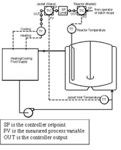
Figure 1. Various split-range (TY) configurations can be used to regulate jacketed glass-lined batch reactors.
Batch reactors generally demand some additional objectives such as:
- fast heatup or cooldown to a new set point without oscillation and with minimal overshoot; and
- stable response to load disturbances, e.g., exothermic reaction.
Achieving these objectives requires paying attention to many details of the equipment and controller logic. Systematic testing and optimization of the feedback control loops also can speed the startup of a new plant.
Figure 1 shows a common control system for glass-lined batch reactors where the slave loop operates on the jacket inlet temperature to protect the lining. The heating/cooling supply can have various split-range (TY) configurations such as control valves to hot/cold headers (which we’ll call Case 1), control valves to steam and chilled-water heat exchangers (Case 2) and control valve on the chilled fluid and variable electrical heating (Case 3). Here, we’ll look at some challenges and opportunities based on real data from three such reactors as seen from the operators’ trend charts. We’ll show symptoms of common problems and examples of benefits achieved.
Case 1
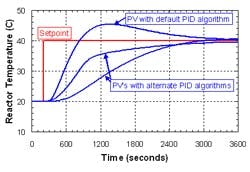
Figure 2. Overshoot afflicted set-point steps on an 800-L reactor with the reactor loop in auto and the jacket loop in cascade.
A plant was starting up a new building with all new reactors, instruments and Distributed Control System (DCS). A consultant applied Lambda tuning (which we’ll discuss later) to give smooth fast set-point and load responses without oscillation. However, as shown in Figure 2, the default Proportional + Integral + Derivative (PID) algorithm produced temperature overshoot that exceeded the recipe specifications on set-point steps. The overshoot is due to the presence of integral action in both the controller and the process. Dominance of integration (slow ramping) in the reactor temperature process may confuse the engineer, technician or auto-tuner responsible for finding the best controller tuning parameters. Integral action is needed in the controller to correct for load disturbances. In a modern control system it’s easy to choose alternative algorithms (Figure 2) to prevent or reduce this overshoot.
If we waited longer for the set-point responses to settle, we’d see a slow limit cycle of ±0.5°C on the reactor temperature and ±5°C on the jacket temperature. The root causes are nonlinearity in the jacket loop from selecting inappropriate control valves and excessive dead zones in the split range strategy. No tuning of the feedback controller will eliminate limit cycles.
Case 2
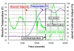
Figure 3. Oscillation occurred during set-point step on a 40,000-L reactor with the reactor loop in auto and the jacket loop in cascade; a load disturbance (exothermic reaction) also took place.
At another plant, temperatures of eight reactors were oscillating. Figure 3 shows a set-point response and a load response for one reactor temperature loop. With the reactor set point initially at 30°C, the slow oscillation caused the jacket to continuously and alternately consume significant quantities of steam and chilled water. Later, after the exothermic reaction, the jacket controller output began swinging almost full scale up and down. Average energy consumption was much greater than that theoretically required to maintain the reactor temperature. There also was a smaller faster oscillation of the jacket loop.
The main problems identified by the consultant and corrected were:
- oscillatory tuning of the reactor temperature controller;
- oscillatory tuning of the jacket temperature controller;
- excessive dead zone in the jacket split range logic; and
- control valve setup problems.
The plant personnel hadn’t been trained in modern loop-tuning methods such as Lambda tuning, which gives nonoscillatory response at the speed required by the production objectives. The tests required for systematic tuning also revealed the nonlinearities in the split range logic and control valves. After applying corrections to three reactors, energy savings on steam alone paid for the consulting project in less than three months.
Case 3
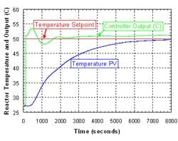
Figure 4. Response was far too slow for a set-point step on a 3,600-L reactor with the reactor loop in auto and the jacket loop in cascade.
The as-found auto response was too slow, taking more than two hours to reach the new set point (Figure 4). Note for the reactor (master) loop the units of the SP, PV and output all are °C. For integrating processes, fast closed-loop response requires driving the output beyond the PV for some period of time. Due to the slow tuning, the operators preferred to make frequent manual adjustments to the jacket set point until the correct reactor temperature was achieved. This interfered with the operators’ primary duties such as sampling for quality control.
Due to nonlinearities in the control logic, it wasn’t possible to find the best controller tuning parameters by hand calculation. Instead the consultant built a computer simulation using test data acquired from manual step responses. This led to much better tuning of the controller and allowed the operators to keep the reactor loop in auto mode — as designed.
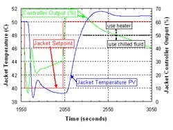
The tests also identified several limitations in the jacket response (Figure 5). The response was much faster to cooling than to heating. The cooling response showed initial oscillation followed by a very slow attempt to recover to 40° C. The asymmetry in heating versus cooling indicates the need for a gain scheduling controller, which applies one set of tuning parameters for cooling and another for heating. Manual step testing of the jacket also showed that inappropriate derivative and filtering values had been installed for the jacket controller. Finally, ideal cooling response would require a different inherent flow characteristic in the cooling valve. Fixing all these problems in the jacket loop would further improve the reactor response.
Methods for success
In the typical chemical plant, there’re several obstacles to achieving optimal control. Plant design and construction often emphasize chemistry, cost and safety instead of control. Academic control courses typically leave the plant engineer ill-prepared due to their emphasis on complex mathematics or sole focus on continuous processes. Early tuning methods, still taught in the industry, were designed to deliberately make the loop oscillate. The jacket and reactor temperature relationship includes integrating dynamics, making controller tuning less intuitive than for self-regulating (e.g., flow) loops.
Complex control systems have been developed to handle various reactor hardware, specific types of chemical reactions and production constraints [1]. For the fastest possible set-point response, you may want to consider a nonlinear control strategy as described in Ref. 2. However, for reactors controlled by simple cascade strategies (Figure 1), many problems can be prevented by applying the following five steps to each loop:
- Make the process dynamics as linear as possible.
- Minimize dead time.
- Measure the process dynamics.
- Choose the right controller algorithm to compensate for the process dynamics.
- Tune for the speed required, without oscillation.
Figure 5. Jacket responded faster to cooling than heating as shown with reactor loop in manual and jacket loop in cascade mode.
means the process temperature PV responds consistently regardless of the size, direction or history of the controller output changes. In the jacket loop, achieving linearity requires selecting appropriate control valves and minimizing nonlinearities in the control strategy, e.g., dead zones in the split range logic. Figure 5 shows another example of nonlinearity: on the heating step, after the initial overshoot, recovery to 50° C was extremely slow due to the control-valve flow characteristic. Sometimes the limiting nonlinearity is in the utilities supplying the jacket, e.g., a steam-header pressure control loop. In the reactor loop, linearity means getting symmetrical set-point responses from the jacket. If the cooling and heating responses of the jacket are asymmetrical (as in Figure 5 or for steam versus cold water), consider a gain scheduling controller to compensate. This doesn’t require any special coding because it can be easily configured by drag-drop-and-tune in modern control systems.Linear
Dead time is the time measured from an output change before anything happens on the PV. It’s inherently destabilizing in a feedback control loop. In the jacket, one cause of dead time is transport delay or the time required for a new fluid mixture to pass from the control valve to the measuring element. Minimize this dead time by appropriate sensor location and by installing a circulating pump as shown in Figure 1. Also, the effect of filters added in the transmitter or the controller may look like dead time to the PID algorithm. In the reactor loop, we minimize dead time by getting the fastest linear response of the jacket loop, including allowing one overshoot on the jacket set-point response.
Process dynamics is a model of the shape and size of the PV response to output changes, which we need to optimally tune the controller. For most loops this can’t be calculated before construction and is most conveniently determined from step tests with the controller in manual. The process dynamics can be manually calculated from trend charts or time series data acquired from an OPC server or, in some cases, automatically by software running in the DCS. The two simplest types of process dynamics are:
- self-regulating processes (those that eventually settle at a new value during manual step tests); and
- integrating processes (those that ramp at various slopes during manual step tests).
The tests to measure these process dynamics also will reveal the nonlinearities in the process.
With a PID controller the type of process determines how to compensate for the process dynamics. For purely self-regulating processes we mainly use integral action in the controller. For purely integrating processes we mainly use proportional action. Derivative action normally isn’t needed in the jacket controller but may be appropriate in the reactor controller.
The Lambda tuning method is one way of choosing the PID parameters to tune for the speed required, without oscillation. For process dynamics that are purely self-regulating or integrating, simple algebraic tuning rules developed for continuous processes [3] have proven applicable to batch processes. These rules can be taught to engineers, technicians and operators as a time domain method — without the use of Bode plots or transfer functions. We must observe the rule of cascade by tuning the jacket (slave) control loop first and faster than the reactor (master) control loop. The Lambda tuning method provides explicitly for tuning by the cascade rule because we can set the response time (λ) of each control loop as:
λ jacket << λ reactor
More-advanced tools are helpful for some situations. If the temperature process response has elements of both self-regulating and integrating dynamics, a different tuning rule is needed. When there’re significant nonlinearities in the control logic (for example, the SP limiter block in Figure 1), a nonlinear computer simulation can accelerate finding the best controller parameters — today’s control systems come with built-in simulation tools. In some cases a Fuzzy Logic Controller (FLC) can give control superior to PID. When there’s no jacket but only electrical heating of the reactor, the FLC can provide the fastest possible heating of the reactor with no overshoot or oscillation. Again, the modern control system makes it easy to install this controller.
Achieve better control
Some plants have experienced oscillatory or sluggish response of batch reactor temperature. This can be caused by the integrating process response, limitations in the control system and lack of training. With a modern control system, a plant can set up the controllers to give fast set-point response without overshoot or oscillations. This offers the opportunity to maximize product quality, minimize batch cycle time and eliminate utilities waste — all positive impacts on your plant’s profitability.
Mark Coughran is a senior process control consultant for Emerson Process Management, Austin, Texas. E-mail him at [email protected].
References
- Process Control and Optimization, Volume VIII in “Instrument Engineers’ Handbook,” p. 1,664, 4th ed., B.G. Liptak, ed., CRC Press, Boca Raton, Fla. (2007).
- Boudreau, M.A. and G.K. McMillan, “New Directions in Bioprocess Modeling and Control,” p. 91, ISA, Research Triangle Park, N.C. (2007).
- Bialkowski, W.L., in “The Control Handbook,” p. 1,234, W. Levine, ed., CRC Press, Boca Raton, Fla. (1996).
