Keep others from making classic mistakes
You probably know some “classic” design problems — ones created by the physics of systems or how equipment works. Many of us get our first exposure to them through university textbooks. However, professors often don’t properly emphasize the importance of these problems, and even if they did, the details certainly can fade from memory over time. So, never presume that everyone is aware of them.
Indeed, when a casual comment leads to blank stares around you or to a surprised “How did you know that?” it’s time to review some basics. Frequently this involves reiterating that the process and the equipment aren’t independent but interact. You cannot separate process constraints and equipment selection.
Recently, I faced just such a situation involving the classic heat exchanger 1-2 problem.
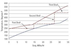
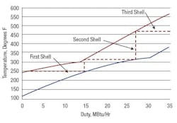
Figure 1 shows the temperature-duty (TQ) curve for a set of hydrotreating exchangers in which the reactor feed is the cold stream and the reactor effluent is the hot stream. A fired heater between the exchangers and reactors adds the extra heat required for the reaction.
Figure 1. Steps between curves show that three shells are the minimum necessary.
A major rebuild of an existing unit mandated a new heater, preferably one that offered ultra-low NOx emissions. Low heater duty was attractive for both economic and environmental reasons — to achieve low fuel consumption and tight combustion-gas limits, respectively. Maximum heat recovery was the objective. The cold feed to the feed/effluent exchanger entered at 113°F. The required reactor inlet temperature was 563°F. A first pass on optimization showed 350°F to 400°F as a good target temperature range for the cold feed out of the exchangers.
My immediate response on viewing the TQ curve was that a minimum of three exchanger shells would be required, with four probably being the most economic. The client looked surprised and asked: “Why do we need so many shells? Since each shell was going to be relatively small, wouldn’t it be cheaper to build fewer shells with more area in each, even if the area was a little less efficient?”
From a heat transfer view, the TQ curve is nothing special. The curves don’t cross, so the service is possible. The minimum temperature approach is 63°F, which is reasonably large. For this service approach temperatures down to 40°F are often economic. The problem comes from how tubular exchangers are laid out. The client specifically wanted to use only TEMA AEU-type shells because previous operation with internal heads had resulted in too many feed-to-effluent leaks.
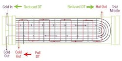
The TEMA AEU-configuration heat exchanger (Figure 2) is by far the most commonly used unit in nearly all industries.
Figure 2. This type of exchanger predominates in a wide variety of applications.
The second letter refers to an E-type shell — a design with one shell inlet nozzle and one shell outlet nozzle at opposite ends of the exchanger. The third letter refers to the rear head type, in this case U-tubes instead of an internal head. The U-tube forces an even number of tube passes in the exchanger. When more than one tube pass is used, the exchanger cannot have true counter-current flow. The exchanger depicted is a 1-2 exchanger (one shell pass, two tube passes).
Inspection of the hot stream and cold stream flow lines immediately indicates a major limitation (Figure 2). The outlet location of the hot stream doesn’t match up with the inlet location of the cold stream. Additionally, the path of the shell-side fluid crosses back and forth across the path of the tube-side fluid. Exchanger design takes this into account by multiplying the calculated log mean temperature difference (LMTD) by a correction factor F determined by the exchanger geometry. The practical and theoretical limitations of the cross flow mean that once the cold outlet temperature rises above the hot outlet temperature extra surface has no benefit. In a single 1-2 exchanger, the outlet temperatures cannot cross (actually they can slightly cross, but not very much).
Once you have a TQ curve for a proposed exchanger service, you can step off a series of lines to show the minimum number of 1-2 (or more complex) shells required. In this case it’s three. However, design optimization showed four shells to be most economic.
Understanding the 1-2 exchanger limitation quickly allows identification of constraints in existing systems and minimum requirements for new systems. While other exchanger choices can address these constraints, nevertheless, for very good technical reasons TEMA E-type shells will remain the most common heat-exchanger type. We should all understand the implications of this.


