Cooling towers play an essential role at many chemical plants. As with any other heat exchanger, maximizing efficiency from the standpoint of both equipment design and protection from fouling, scaling and corrosion is crucial. With cooling towers, fill selection is a critical aspect in this regard. At first glance, high efficiency film fill may seem the most desirable option. However, if poor water quality causes this fill to rapidly foul and plug, it may incur excessive maintenance costs. So, here, we’ll examine the fundamentals of fill types and also look at important chemistry issues that influence selection. Proper makeup-water pretreatment may enable selecting a higher efficiency fill than otherwise possible.
Figure 1. Plants typically rely on either an induced-draft crossflow (left) or counter-flow (right) design.
Figure 1 shows schematics of the two most common types of industrial cooling towers, induced-draft crossflow and induced-draft counter-flow. Both of these use air to remove heat from water fed into the tower.
Ambient temperature and humidity influence performance, and typically 65–90% of heat transfer in a cooling tower comes from evaporation of a small portion (1–3%) of the recirculating water. Thus, an underlying guideline for all cooling towers is to enhance air/water contact. In the beginning, this was accomplished through the use of splash fill — a series of wooden slats placed in a staggered formation below the water spray nozzles. As water impinges upon the slats, it breaks into small droplets that increase the surface area.
Fill has evolved significantly from that rudimentary splash fill design. Most cooling towers now utilize film fill to enhance air/water contact. Film fill, as the name implies, induces the cooling water to form a film on the material surface. The filming mechanism maximizes liquid surface area. A guiding principle behind fill design and selection “is to increase air-to-water contact, driving up convection and evaporative cooling while reducing pressure drop in the system” [1]. Fills generally are made of polyvinyl chloride because of its low cost, durability, good wetting characteristics and inherently low flame spread rate.
Fill Selection
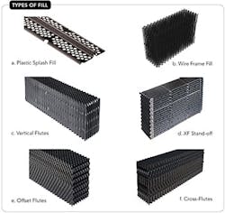
The choice of fill design in large measure depends upon the fouling tendencies of the cooling water. Figure 2 illustrates a variety of fill designs ranging from modern splash fill to very high efficiency material.
The most basic and least expensive is plastic splash fill (Figure 2a). An advancement on this technology is “wire frame” fill. In one type of wire-frame design, water film cascades on the strand surface; cooling occurs predominantly via film generation, with droplet generation only incidental. This fill typically comes in a modular cross-fluted design. The other wire frame design uses a multitude of integrated drip points to create a compact volume of droplets (2b). These “modular splash” (M/S) fills usually have offset flute geometry and are inherently more fouling resistant than cross-fluted fills. Reference 1 provides more information.
The others options consist of film fills. These have air/water passageways called flutes. A variety of flute configurations are available, with each reflecting a different tradeoff between thermal performance and fouling resistance.
Vertical film fills such as vertical flutes (VF, 2c) offer a straight path for water and air flow. Thermal performance is lower than that of higher efficiency designs but VF fill has excellent anti-fouling characteristics.
XF stand-off fill (2d), which is made specifically for crossflow cooling towers, boasts a high specific surface area and moderate-to-good anti-fouling tendencies depending upon water loading.
Figure 2. Choice of fill largely depends on the fouling tendencies of the cooling water. Source: Brentwood Industries.
Offset flutes (OF, 2e) also have high specific surface area, and force the water and air through a moderately tortuous path. Thus, anti-fouling characteristics are moderate, too.
Cross flutes (CF, 2f) typically provide high specific surface area and high thermal performance but exhibit poor anti-fouling characteristics due to the geometry that forces many deviations to the flow path.
Flute spacing significantly affects fill performance; smaller spacing increases the surface area but also raises the potential severity of fouling.
Many investigators have pointed to bio deposits as the key trigger of film fill fouling. The scenario for fouling is: biofilms form on the fill surface and collect suspended solids from the cooling water due to the inherent adhesive properties of the bacterial secretions.
The velocity of the water film passing over the deposit surface influences the stability of bio deposits. Higher water velocities minimize biofilm thickness. So, fill manufacturers have developed designs that maximize water film velocity and the resulting high shear stress. The flute geometry of these low fouling fills has a vertical orientation as opposed to the angled orientation (cross flute) of high efficiency fills. These higher water velocity designs exhibit lower thermal performance than their CF counterparts.
CF fills provide maximum surface area for heat transfer but impart a higher pressure drop through the tower than other designs. Also, the lower water film velocity developed within these fills can lead to low flow regions, increasing the fouling potential.
Selecting the proper design requires a careful evaluation of water conditions. Table 1 outlines guidelines for fill selection with various quality waters, ranging from <1,000 ppm to <25 ppm of total suspended solids (TSS) and 0 to <50 ppm of oil and grease.
That table underscores the impact of biological control on fill selection. Yet, as I personally can attest, microbiological control in cooling systems, even once-through networks, can be a challenge. However, suitable care in the design and selection of chemical feed programs and makeup-water pretreatment equipment may enable use of higher-efficiency fills in applications where they otherwise wouldn’t make sense.
Oxidizing biocide treatment is essential for all cooling water systems. Chlorine, usually supplied as bleach or generated on-site, is the most common choice, although the effectiveness of chlorine rapidly diminishes as the pH rises above 7.5. Many natural waters have a pH near 8, which often leads to selection of alternative oxidizers, most notably chlorine-activated bromine, chlorine dioxide, monochloramine and monobromamine. In many cases, oxidizer feed is limited to two hours per day, which gives microbes time to settle and form colonies during off times. A supplemental feed of a non-oxidizing biocide, say, on a once-per-week basis, can quite effectively control microorganisms. Table 2 lists properties of some of the most common non-oxidizers.
Careful evaluation of the microbial species in the cooling water is necessary to determine the most effective biocides. Do not test, let alone use, any of these chemicals without approval from the appropriate regulating agency. They must be incorporated into the plant’s National Pollutant Discharge Elimination System permit. Also, as with all chemicals, safety is an absolutely critical issue when handling the non-oxidizers.
Other Factors
The use of alternatives to fresh water for plant makeup is becoming more common. One increasingly popular source, either by choice or mandate, is effluent from a publicly owned treatment works, i.e., municipal wastewater treatment plant discharge. These streams often have significant concentrations of ammonia, nitrite/nitrate, phosphate and organics, or in the industry vernacular, “bug food.” Untreated, such makeup water can cause explosive growth of microorganisms in cooling systems. Sophisticated pretreatment of the plant makeup usually is necessary, with two increasingly common options being membrane bioreactors and moving-bed bioreactors.
Another factor that influences fouling is the suspended solids’ concentration in the water. Any microbiological colonies that do become established in fill or heat exchangers typically secrete a slimy film for protection. This slime naturally captures silt. A treatment method that is regularly recommended for cooling towers — but often isn’t adopted — is sidestream filtration. Information about sidestream filtration is readily available from a number of sources, most notably the Cooling Technology Institute.
BRAD BUECKER is a senior technical publicist for ChemTreat, Glen Allen, Va. Email him at [email protected].
ACKNOWLEDGEMENTS
The author wishes to acknowledge Rich Aull, retired from Brentwood Industries and now president of Richard Aull Cooling Tower Consulting, LLC, for providing substantial assistance with this article, and Bill Miller of Brentwood Industries for photos of the various types of fill.
REFERENCES
1. Zaorski, A. and W.C. Miller, “A Study on Bio-Fouling Characteristics of Contemporary Trickle and Modular Splash Fills,” presented at the 2017 Cooling Technology Institute Annual Conference, New Orleans, La. (February 2017).
2. Wallis, J. and R. Aull, “Improving Cooling Tower Performance with Thermal Fills,” Process Cooling & Equipment, March/April 2000.


