This Month’s Puzzler
Our refinery sells propylene to a polymer manufacturer. The railyard loading system (see figure) at the edge of our site usually gets little attention; I reckon it largely has been ignored for decades. However, the system drew management notice when we went through a patch of extremely cold weather. The frigid temperature caused the air lines to the control valve to plug when moisture in the lines froze. When I went to sort out that issue, the foreman was eager to share his other troubles: 1) the pump vapor-locks; 2) the compressor starts and stops too frequently, leading to too rapid replacement of the motor starter heaters; 3) the pressure relief on the compressor pops open often and sticks open; 4) the measurement from the orifice plate is erratic; 5) the pump frequently must go to the shop, mostly to replace seals and bearings; and 6) units at the refinery can’t agree on an outage schedule to allow shutting down system for cleaning and maintenance. What can I suggest to improve this operation?
Take Another Look At Controls
Here’re my thoughts.
1. Pump vapor lock:
a. The type of pump is not specified but needs to be examined. LPG [liquefied petroleum gas] usually demands a multi-stage pump, one more exotic than a centrifugal. Most LPG pump cavities usually have a vapor-removal capability.
b. It looks like the flow from the pump is controlled by the flow controller to the car, which is fine. However, what is that flow rate controlled at? Is that rate operator-set and dependent on whether he wants to fill it fast or slow? Is the pump started or stopped between cars? If so, there may be a tendency to have the pump running between cars. Even a momentary stop will dead-head the pump and cause it to heat up. Whatever the setting, be sure that it is one on the pump curve. Too high or too low could cause the issue you are seeing.
c. It appears that there is no minimum flow on the pump. If there were a line between the pump discharge back to the suction or tanks, then a control valve could open to take flow back to the tanks and always maintain pump at minimum flow. A local flow control valve at the rail car station could control the rate the car fills.
d. Also, I don’t see a drain line on the tanks. LPG streams from all over can be saturated or carry some water or oils. These should be routinely drained from the tanks so they do not get to pump.
2. Compressor start/stop:
a. I’m not sure why there is even a compressor there. Cars can be opened to the vapor line at the top of the active tank and the whole system run at product vapor pressure at atmospheric.
b. If you feel you must keep the compressor, a line to the discharge line with an orifice would allow the compressor to keep running between fills and shut down when the day is done.
3. Pressure safety valve (PSV):
a. You should ensure the PSV is in the vapor space or at the top of the vessel. Vapor valves don’t do well in liquid service and vice versa. If the PSV is immersed in liquid, significant flashing could cause valve failure.
b. If there is a buildup of N2 in the vapor space of a tank over time, possibly caused by cars coming in with N2, then they could lose saturated pressure and actually build pressure on loading of the tank. I see no pressure transmitter or vents on the tanks, so you may not even know this is happening.
c. What is causing over-pressure? I do not see a tank pressure control nor is one needed as the tank runs at material ambient vapor pressure. If the vapor compressor is kept running or if the FV to the tank would pop open, there may be enough of a swing to pop the valve.
4. Orifice:
At saturated conditions, and if the pump is adding heat, there will surely be flashing across the orifice. The signal could be filtered to help the reading but very little else can be done unless back pressure is maintained downstream of the plate. A FCV that doesn’t go wide open (minimum open on the controller) may be all that is needed.
5. Scheduled turnaround:
There really is no need for much cleaning of the system. You have double filters on the pump suctions.
Tom Brader, staff instrument engineer
Valero, St. Charles, La.
Learn Some Lessons
It seems that the company up and down the chain of command has been sleeping at the helm. It has to own up to the neglect. Instead of asking for solutions, it is best that the company use its own maintenance department or a local contractor who can be on routine preventive maintenance detail. Whoever is used has to be very familiar with the operation and its needs.
I am surprised at the gross neglect especially at a refinery. In addition, that the foreman was eager to share other issues suggests poor human resource management at the site. The company is fortunate that they have not had a major accident or a catastrophe.
Please get a competent maintenance staff before a catastrophe occurs.
Girish Malhotra, president
EPCOT International, Pepper Pike, Ohio
Replace The Pump
LPG and propylene loading systems seem to be the forgotten stepchildren at most refineries. Like many utility systems, they take in products from many units that only want to get rid of the stuff.
Pumps usually aren’t the most reliable way to move LPG and propylene. There’s always a challenge keeping the liquid from vaporizing and causing issues in flow control and mechanical seals. At least the design engineer took the care to consider pressurizing the bullets. I’ve seen people at refineries wonder why they couldn’t move more liquid when they let the bullet pressure drop below liquid vapor pressure. As I recall, the project engineer tried to fix the problem of a wet gas going to a tanker truck by installing a valve with a larger Cv value.
The best way to present improvements is to provide two options: the economy package and big-ticket package. I suggest that the economy package, to handle short outages, include a number of minor improvements:
1. I assume you found that the instrument air was a little wet. Being a remote location, you should either install a dedicated compressor with a dryer or a desiccant dryer controlled by the foreman. That should make him happy.
2. The suction line is too small — 4 in. gives a velocity of over 8 ft/min — the maximum velocity recommended for LPG is 7 ft/min; propylene is much more volatile, so a lower velocity is recommended. A high velocity means a high pressure drop with gas/liquid flow. Tap into the 24-in. equalization line to reduce the overall velocity.
3. Get rid of the strainer. Notice that the suction line has a riser in it. This is a no-no with LPG, propylene and any other liquid that could become saturated with gas. Someone shoe-horned the strainer in because the strainer’s internal lines are smaller than the suction line. It’s a common problem in coordinating a project: equipment is ordered and something changes in the layout. The proper solution was to lower the pump and suction line to eliminate the riser. Replace the strainer with a simple basket strainer. Also, check to see how often the strainer differential pressure causes the alarm to chirp: you may not need anything more than a coarse strainer.
4. Move the orifice flow meter to a spot where it can read all liquid or all gas. I’d suggest replacing it with a vortex or even a Coriolis meter but they all are equally sensitive to mixed flow. The stream is most likely to be liquid at the immediate discharge of the pump. Of course, this violates a standard rule about measurement being close to the control valve; ignore it in this situation.
5. Install a surge tank after the compressor. Put the pressure controls there. This adds deadtime to the measurement, a good thing in this case.
6. Add a tank immediately in front of the pump and feed off the bottom. Don’t worry about the gas in the tank. Consider chilling the tank to account for the heat added by the pump by entropy.
7. Lastly, consider adding separate bullets upstream of these tanks. Part of the problem for the foreman is lack of control. If each unit had its own bullet, he’d have more control over his own unit; these bullets could be used during an outage to allow maintenance on the loading system. In addition, this would enable quality control of the feed coming to the bullets.
The best solution would be to replace the pump completely. Use a much larger compressor to pressurize the bullets and siphon the liquid to the railcar. Anytime you can replace a pump for a compressor with a wet liquid, take it.
Dirk Willard, consultant
Wooster, Ohio
June’s Puzzler
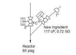
We’re having trouble with a reactor addition valve (Figure 1). It handles a minor ingredient that we add occasionally for a new product. We’re hoping to expand our business — and the valve is critical to that expansion. However, the addition valve is giving us trouble. I want to sort the problem out before the new product becomes a major part of our business.
Figure 1. Contamination from new ingredient and caustic afflict operation.
We see traces of the new ingredient in quality testing. We see traces of caustic soda in the product, too.
I’m suspicious of the valve tee arrangement and the valve actuator performance. In addition, I want to pin down the source of the caustic soda. The main line is seldom down but the piping for the new ingredient gets periodically flushed and cleaned using a protocol of water flush, caustic wash and then water flush again. The flush return is upstream of a 2-in.-to-1-in. reducer.
What should I do to eliminate this contamination problem?
Send us your comments, suggestions or solutions for this question by May 11, 2018. We’ll include as many of them as possible in the June 2018 issue and all on ChemicalProcessing.com. Send visuals — a sketch is fine. E-mail us at [email protected] or mail to Process Puzzler, Chemical Processing, 1501 E. Woodfield Rd., Suite 400N, Schaumburg, IL 60173. Fax: (630) 467-1120. Please include your name, title, location and company affiliation in the response.
And, of course, if you have a process problem you’d like to pose to our readers, send it along and we’ll be pleased to consider it for publication.


