Engineering models can play a significant role in improving plant efficiency and safety. Software modularization, user interface innovation and computing power increasingly open up opportunities for models in operations.
This growing potential makes it even more critical to re-use the same models to solve different problems across the asset lifecycle and at different levels of granularity in operations. After all, a simulation that reliably predicts a particular application and situation becomes much more valuable if it can be applied to all tasks that require modeling of that unit or process. Indeed, the broader use of these models promises to have a profound business impact. So we’ll describe current trends toward re-use of models and the integrated workflows that result.
First, though, let’s set the stage by briefly summarizing the business challenges that are spurring the use of modeling technology to address a complete plant lifecycle:
- Pressure of global competition imposes the need to accelerate engineering, reduce capital costs and optimize operations. This increases the value of having one common set of models that can be used from process synthesis through to plant operations and debottlenecking.
- Rapidly rising cost of energy and secondary cost of greenhouse gas emissions require the redesign and optimization of processes. Models suitable for use by design, plant engineering, compliance and operations groups are a key tool.
- Shortages of skilled veteran engineers will continue over the next decade. Effectively transferring optimization expertise to new staff demands increasingly powerful and easy-to-use models that capture organizational knowledge and experience.
These challenges call for moving to common models to solve multiple problems, making models simpler to use, and integrating models with other software to solve broader business problems. Today’s integrated modeling tools already attack many of these areas and the technology continues to evolve.
Key trends in modeling
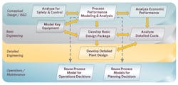
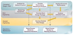
Figure 1. Process models can play an important role in all four phases.
- Initially modeling tools were developed to solve specific problems such as energy analysis, heat exchanger design, dynamic analysis and cost estimation. Next industry began to build links between these individual tools so they could share information and data. Then, with development of process data models and modularized tools, links evolved into real integrated process simulation workflow (Figure 1). This integrated approach yields time, cost and quality benefits. (Such streamlined workflow also offers advantages to engineering firms, which face increasing pressures to efficiently execute projects with fewer engineers. [1])
- Process models originally developed for front-end engineering design (FEED) now are being used in plant operations. Owner-operators increasingly rely on models to support operating decisions, to optimize processes in real-time and to improve the accuracy of planning systems.
Let’s look at some ways integrated modeling now is providing value:
Simulation/economics work process. The integration of economic analysis with the basic process development activity yields sizable benefits. Process engineers don’t need to wait until a formal package is handed over to the estimating department before gaining accurate understanding of the economic trade-offs between alternative designs. Process costs are calculated and optimized concurrently with the conceptual process development, allowing the engineers to better understand the economic impact of their design decisions.
Fluor, which calls such integration “cost optimized design,” cites a number of benefits [2]. These include the ability to focus on technology/cost trade-offs early, improved quality of estimates and better cost awareness during design.
BASF estimates it saves 10% to 30% in capital costs and up to $2 million/yr. in energy through its i-TCM (intelligent Total Cost Minimization) project approach, which involves performing process simulation, cost analysis and equipment modeling in parallel [3]. The goal is to optimize capacity, reduce operating costs and develop better designs for new or revamped plants.
Design/operability workflow. The use of dynamic models for safety and operability analysis is another advance. This clarifies whether a design simulation solution is stable under real-world dynamic conditions. The goal is to use the same unit operations models for both steady-state and dynamic analysis, avoiding having to develop the models again.
Shell Chemicals takes this approach to model reactor and relief systems to ensure that designed safety systems will be able to contain any runaway reactions. This application of dynamic modeling improves operations safety and reliability and saves operating costs through optimized normal operations [4].
Conceptual/basic/detailed engineering workflow. Integrated basic engineering represents another area where workflows have advanced. The heat and material balance and flow sheets from simulation studies are directly input into the basic engineering process, where multiple disciplines define the FEED and then pass that information to detailed design.
WorleyParsons, by linking together process simulation, basic engineering and detailed design, achieves an estimated 25% increase in engineering efficiency and 50% reduction in time for basic engineering [5].
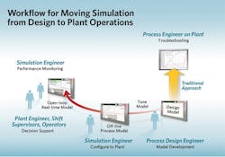
Figure 2. New uses of design models in operations require changed workflow.
Models developed during process development and design phases of a plant represent significant engineering effort and knowledge. The design benefits include engineering productivity and reduced capital expenditure/plant lifecycle costs. Re-using those same models within the plant operating environment can provide even more benefits.Moving models from R&D/engineering into plant operations.
Process models suitable for use in plant operations span a spectrum from off-line steady-state simulation to debottlenecking analysis through to closed-loop real-time optimization of process performance. Table 1 highlights the different levels of benefit and implementation time and effort. Figure 2 illustrates the typical workflow in taking design models into operations.
Making the transition
Type of model |
Used for |
Description |
Traditional process simulations |
Troubleshooting, debottlenecking, process revamps |
Used by plant-based engineers on an “as required”basis to support plant operations |
Off-line process models |
Supporting operational decisions, advising operations, reconciling plant mass balances, calculating product properties, training process staff |
Used daily, weekly or whenever neededTypically have a customized user interface in Excel or Visual Basic May link to some real-time data Initiated by a person
|
Real-time open-loop models |
Calculating and advising on optimal plant operating conditions to maximize financial performance |
Typically used each shift, daily Automatic model execution Person accepts or rejects any operating advice
|
Real-time closed-loop models |
As for open-loop models |
Interface directly with plant control system and adjust the process automatically |
Table 1. Real-time models are more capable but take more effort to make robust. |
||
- advising on operating set points for individual equipment items;
- achieving a reconciled plant mass balance;
- determining product properties;
- analyzing energy usage;
- comparing actual versus design performance;
- responding to changing market conditions;
- meeting product specifications; and
- retaining and enhancing process knowledge.
Even though they may connect to real-time data systems, off-line models aren’t fully automated; a person normally initiates runs.
Models produced during the design phase usually require additional work before they can be used as off-line process models. After all, in design the simulation is created and run by an experienced engineer, who understands the constraints of the model and the range of valid conditions. If difficulties such as convergence failure occur, the design engineer knows how to overcome such problems.
For use in operations, the model must be tuned to match plant conditions and the particular calculations being executed. For instance, the plant setup may change from day to day — with different product grades being produced and individual units or controllers switched on/off. The off-line process models must account for these specifics.
In addition, because the simulations only are valid within a limited range of operating conditions this range must be strictly understood and enforced. The models will need to be made robust, so they always converge within the valid operating ranges. Model inputs (both those entered manually and those coming from real-time data systems) must be kept within these ranges; this often is done by running the models through a simpler custom interface, such as one based on Excel instead of their normal “engineering” user interface.
The sidebar provides other practical pointers for moving models from design to operations.
The next steps
If an off-line process model gets regular use in operations, it may be appropriate to convert it to a real-time open-loop model. The model execution then can be automated to occur, say, once per shift, every N minutes or when triggered by a process event. Such open-loop models also may write results back to the plant’s real-time data systems. However, the results of the model are always evaluated by a person, who ultimately accepts or rejects any advice or data.
| When moving models from design into operations, pay particular attention to the following points: |
|
Additional effort is necessary to make these automated models even more robust, read in additional real-time plant data and reconcile conflicting plant data (e.g., measured mass flows in and out of a unit that don’t balance).
The final level of modeling in operations employs real-time closed-loop models, with their results implemented in an automated way to optimize processes. These systems require additional effort to make the system fully robust and safe. However, they promise even greater benefits, particularly where processes need to respond to predictable variability (e.g., in feedstock characteristics).
Chemical companies already are realizing significant benefits in plant operations from each of these approaches [6]. The experience reported by INEOS is instructive. It used a modeling approach to optimize heat exchanger monitoring and cleaning in its vacuum distillation units, saving more than $3 million dollars per unit per year [7].
Future directions
The biggest challenges in integrated engineering are along two fronts:- for collaboration between engineering disciplines; and
- for moving rigorous analytical models into the operating environment.
The effort required to build discipline-specific and plant-specific models coupled with the need to hide the complexity of these models from people performing specific roles have driven innovations in modeling tools. Here are some key developments:
Modularized systems. Process modeling systems can be redesigned for re-use in a modular fashion throughout an asset’s lifecycle. One example is the physical properties database. AspenTech now offers its as a re-usable resource, a “standardized component” for a number of different model-based applications. This ensures maximum flexibility and consistency regardless of choice of modeling tools.
Another example is the unit operations models. These can be modularized so they are usable by systems ranging from simulation, basic engineering, optimization, economic evaluation to advanced process control.
User console and simplicity. New concepts build the workflow right into the user interface — presenting the appropriate analytical models and tools to users depending upon their role, the phase of a project and their position in the workflow.
Models in engineering. This provides the capability to call models from downstream in the design process, including basic design, start-up and control (without looping back to the modeling group). Modeling can be performed in-plant without intervention by design engineering.
Common engineering data backbone. A lifecycle database incorporates unit operations models, process, equipment and instrumentation data and control information to facilitate lifecycle optimization.
Realize real benefits
Process engineering models created during conceptual design increasingly are being applied downstream in the design process and operations, thanks to developments that make these analytical models usable by other disciplines and plant staff. This is leading to measurable savings in dollars, energy, time and staffing.
Future work by software innovators will lead to the modularization of unit operations models and increased ease of use and integration of work processes. Rigorous models are destined to become even more widely used and more valuable tools in the operation and optimization of process facilities.
**Rob Hockley is a Warrington, U.K.,-based senior consultant for Aspen Technology, Inc. Ron Beck, is marketing manager for Aspen Technology in Burlington, Mass. E-mail them at [email protected] and [email protected].
References
- Mullick, S. and V. Dhole, “Consider integrated plant design and engineering,” p. 81, Hydrocarbon Proc. (Dec. 2007).
- Lofton, W. and L. Dansby, “Adding value by integrating process engineering concepts and cost estimating,” Presented at AspenWorld 2002 Conference (Oct. 2002).
- Wiesel, A. and A. Polt, “Paradigm shifts in conceptual process optimization,” AspenTech User Group Meeting, Frankfurt, Germany (Apr. 2007).
- Donkers, M., “Runaway reaction hazard assessment within Shell International Chemicals,” available online at www.safetynet.de.
- Cox, R. et al., “Can simulation technology enable a paradigm shift in process control? Modeling for the rest of us,” p. 1,542, Computers & Chem. Eng. (Sept. 12, 2006).
- Pres, R. and P. S. Peyrigain, “Minimizing VDU heat exchanger fouling through application of rigorous modeling,” presented at Aspen HTFS Annual User Group Meeting, Cologne, Germany (Dec. 2006).
- Griffith, J. et al., “Advances in front-end engineering workflow and integration,” p. 32, Hydrocarbon Eng. (Jan. 2008).


