When evaluating adding new equipment, many engineers request reference contacts in other plants where such units already are installed. This is a valuable approach to verify that proposed equipment will really work as required. However, make sure you understand the potential process differences between your application and the one at the other site or you may wind up unpleasantly surprised.
Consider what happened at one refinery that was considering adding backwash filters to remove particulate from the feed to a hydrotreating reactor. If left in the feed, the particulate plugs the hydrotreater catalyst, reducing catalyst life.
The backwash filter removes the particulate. When filter pressure drop becomes too high, the bank of filters goes into backwash mode. A local programmable logic controller (PLC) takes one filter in the bank out-of-service and then feeds a separate backwash fluid to remove the particulate accumulated within it.
The filters require about-30-psi pressure differential between the backwash fluid inlet and outlet. Of course, you need to have somewhere to send the particulate in the backwash fluid stream. In this case, the particulate could be moved into the product of the unit.
The project engineer dutifully contacted the vendor-supplied references. In fact, he actually visited one of the plants. Its experience with the filters was excellent. They ran well and achieved the desired catalyst life extension. The project engineer returned to his facility ready, eager, in fact, to get the filters installed.
But, unfortunately, he had missed something important. He didn't realize that the plant he visited had downstream surge capacity to handle the flow spikes from backwashing. That plant had a large upstream surge volume as well. His plant lacked both.
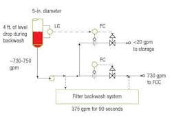
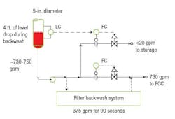
The proposed location for the backwash fluid supply was at the end of the hydrotreater process at the hydrotreater stripper tower boot (Figure 1). Backwash liquid was to come downstream from the tower bottoms pump, go to backwash, then to the feed to the downstream fluid catalytic cracking unit (FCC). The FCC unit didn't have any surge capacity. The flow was directly to the FCC reactor.
Figure 1. This setup suffers from four problems that can lead to major operating upsets.
A close look at Figure 2 reveals a host of problems. First, the level controller is on a very small fraction of the total bottoms rate. This is a fundamental problem with the unit and worthy of its own discussion in the future. Adding the backwash draw makes the level control problems worse. Second, the backwash flow required creates a sudden drop in tower bottoms level. Third, the sudden spikes in backwash flow dramatically affect downstream FCC operation. Fourth, these sudden spikes in flow downstream create pressure balance problems in the piping. This configuration promises to be a continual source of major operating upsets.
Solving this problem requires two sets of changes. The upstream inventory capacity must be increased; this is done by removing trays from the stripper tower, raising the level span, and adding a temporary reset on bottoms level control based on a backwash system signal. The downstream surge handling capacity also must be increased; this necessitates adding a surge drum for the FCC feed stream.
Effective handling of liquid surges is essential for making the entire backwash system work. Once the importance of this and the need to add surge capacity became clear, the scope of changes dramatically increased.
This episode underscores two key points: Few installations match exactly; so it's critical to determine the differences. It's also crucial to understand the dynamic behavior of a process as well as its steady-state operation.
About the Author
Andrew Sloley, Plant InSites columnist
Contributing Editor
ANDREW SLOLEY is a Chemical Processing Contributing Editor.


