January Process Puzzler: Sticky valve
Question from November's Chemical Processing
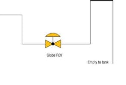
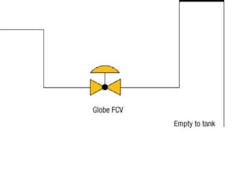
During our plant shutdown a flow control valve was replaced. The globe valve charges a reactor used for making a volatile organic chemical, an intermediary to a polymer (Figure 1). The previous valve faithfully served for several years, though we had trouble with it once because the heat tracing failed. The board operator said that flow dropped to about half, which took longer to fill the reactor. Although the new control valve served well for a few weeks its now sticking and its getting worse. For some reason, the flow problem also has returned. Obviously, we need to pull the valve. What should we be looking for?
Inspect the packing
My knee-jerk response would be to inspect the packing. There may be an undisclosed change in material by the manufacturer (or vendor) which is incompatible with your organic. Engineering is probably at fault but not if there was a material substitution at the shop.
William T. Wolf, principal research technician
Air Products & Chemicals, Inc., Easton, Pa.
Focus on the valve material
Heres my checklist for identifying the valve problem. First, the gasket could be the wrong specified material, and the gasket has started to warp, bend, or swell, resulting in the valve operating incorrectly. We have had the valves grub screws fail, so the actuator turns, but the valves stick. The heat tracing is a minor problem.
Ryan Anicete, mechanical engineer
Ausenco Limited, Brisbane, Australia
Look for polymerization
When pulling a control valve for a polymeriz-able reagent, I would look for a build up of material. A hot spot in the heat tracing can initiate polymerization. Such hot spots could cause polymerization to start forming low-molecular-weight oligomers that could build up in the valve or on the valve stem. Check the packing around the valve stem as well for leaks through which the reagent can pass and accumulate, again providing the opportunity for low level auto-polymerization. Assuming that the heat tracing is hot, the next step is to make sure it isn't getting too hot. Additionally, confirm that the heat tracing was properly reinstalled on the new valve during the change-out.
Kenneth Russell, consultant
Gateway Services, Seabrook, Texas
Focus on heat tracing failure
From the problem description, it seems some of the organic material fed to the reactor or being produced in the reactor is vaporizing and might be sticking and building up on the outlet of the valve, thus blocking the flow. This also is being suggested by the statement the new control valve served well for a few weeks its now sticking.
The heat tracing used on the valve might not be adequate to melt the material stuck at the outlet of the feed valve. If you remove the valve and see a material build up, it will confirm lack of heat to keep the material fluid. The statement old globe valve had a problem due to tracing failure also is suggesting failed heat tracing led to feed problems. This also confirms that the organic material freezes and slows the flow.
Since the product isnt being affected, its a confirmation that all of the necessary feed material is going in but taking longer due to blockage. Self-regulating heat tracing where the temperature can be controlled above the melt point of organic material should alleviate the problem.
Of course, its possible that the problem is engineering. One would expect that the engineer should use the valve with similar attributes, which had worked earlier. The valve should be removed and inspected. If the fault lies with the vendor or engineering, it will be quickly realized after disassembly.
Girish Malhotra, president,
EPCOT International, Pepper Pike, Ohio
Check the installation
I assume the previous heat tracing failure and resulting loss of flow were caused by a high viscosity; when the temperature of the fluid drops, the viscosity increases, and the flow-rate in the line drops off considerably. We experience the same thing trying to pump oil from an un-insulated tank in the winter. I would check the valve to see if its adequately heat-traced as an initial inspection. The tracing control panels may help or you may need thermography. If the heat tracing is steam, some of the steam traps may have failed. Thermographs or ultrasonics will help you identify which traps arent working. There are a few other items on the inspection checklist.
Was the valve installed in the correct flow direction? If it wasnt, the stem and plug of the valve could be exposed to the feed fluid when the valve is closed. Often, during a shutdown, theres a lot of contract labor on-site. These contractors may not be familiar with the facility. The valve installation could easily have slipped through the QA/QC or PSSR process, especially once it was insulated. Problems with the valve installation, like the heat tracing and orientation would be concealed. A loss of heat tracing would have other, more insidious effects.
If the reaction process is a batch reaction, the time that the valve spends closed would allow the fluid to gum up on the plug and stem of the valve if not kept at temperature. When the valve opened, the stem would travel up into the packing and contaminate the packing with the fluid and would cause the valve to stick. The flow would drop as well when the increasingly viscous fluid restricted the passages in the globe valve. When you remove the valve, you will probably purge most of the evidence out of the valve body and the packing gland will be one of the only places that may still have evidence left inside of it. Thoroughly check the packing of the valve for the process fluid and excessive wear. Take a camera to the shop and photograph the stem and seat before the valve is cleaned.
I also would check to make sure that the new valve is a like-for-like replacement of the old valve. In many instances, the group specifying and purchasing the valve arent the people that operate or maintain the valve. The new valve may be quite a bit different than the old valve and you should verify that the port size, trim, packing, and seals are all the same material as the old valve.
Brad Piggott, engineer
Air Liquide America, Houston
Review past history
I believe that one should look at the history of past failures which sometimes give enough clues to solve the problem if it isnt altogether a new problem. In a well proven process, a new problem cropping up is rare. Start with the simple things. Tracing is provided to keep the line at certain minimum temperature to avoid solidification. There is a history of one tracing failure causing flow problem. It doesnt seem logical that piping is a problem. It has worked without trouble for many years. I would pull the valve during the next scheduled maintenance and have it checked for internal troubles. The past history should be checked for similar failures at predetermined intervals.
Rashtriya- V.S.Nandekar, chief engineer
Chem. & Fertilizer Ltd., Mumbai, India
Could it be thermal expansion?
Perhaps the problem lies in different expansion rates of metal parts within the valve. The clue is the problem occurred before when the heat tracing failed. The external metal is cooling as the outside air gets colder. The internal fluid stays slightly warmer causing a differential. Increasing the insulation on the valve and checking the heat tracing effectiveness at the valve might solve their problem.
John Mattson, market manager
SACHEM, Austin, Texas
March's Puzzler
We are formulating a plan for collecting mercury from the blowdown in our scrubbers. Our on-site contractor has provided a basic design for consideration involving ion exchange (IX) and sulfide vacuum filtration (Figure 2). The proposal is for continuous removal of mercury using the maximum concentration range of 1.5-2.0 μg/l as a design basis (EPA studies). The proposal includes a reference to separation processes developed by the U.S. Department of Defense and Department of Energy to handle mercury waste. According to these studies, using sludges of heavy metals, a recovery of 99% can be assumed for the ion exchange. The regenerated waste produced by the IX unit will be treated with a sulfide and run through a vacuum filter: filtrate will then be reprocessed through the IX unit while sludge is collected for disposal. The vendors sales engineer claims that it may be possible to turn a profit by distilling mercury from the solid waste collected after dewatering. Are there any flaws in the proposal? How should we proceed?
Send us your comments, suggestions or solutions for this question by February 16, 2007. Well include as many of them as possible in the March 2007 issue and all on CP.com. Send visuals a sketch is fine. E-mail us at [email protected] or mail to ProcessPuzzler, Chemical Processing, 555 W. Pierce Rd., Suite 301, Itasca, IL 60143. Fax: (630) 467-1120. Please include your name, title, location and company affiliation in the response.
And, of course, if you have a process problem youd like to pose to our readers, send it along and well be pleased to consider it for publication.


