Vision technology no longer is limited to discrete sensing applications, military reconnaissance or deep-space exploration applications. Advances in computer chip technology in recent years ," combined with price reductions ," have made vision systems more attractive to the processing industries.
New manufacturing technologies allow chips to pack exponentially more circuitry, which translates into higher power and faster processing capabilities that allow PC systems to handle the enormous computation load of vision analysis in real time. Such systems offer unique performance features no other instrumentation can provide to control level in a process.
Vision technology based on compact charge-coupled device (CCD) cameras can offer excellent access to an industrial process, providing operators with information about level, color, foam presence and other process conditions. The technology is not dependent on the CCD unit; users can install complementary metal-oxide semiconductor (CMOS) CCD units or other combinations required by the specific application. Information technology (IT) systems even can distribute video of process conditions across the Internet to link manufacturing with engineering in real time.
The silicon eye
A vision system, consisting of a camera and light source, functions in much the same way as the human eye and brain collaborate. If you look at an object on your desk, your eye recognizes it because it has a different color or reflects light differently than your desktop reflects it. It is these changes in reflected-light intensity that make the object visible.
That is precisely how a vision system determines tank content level. A camera looks into a tank and determines the fluid interface with the tank wall because the wall is offset 90 degrees from the fluid surface and reflects light differently (see Fig. 1). It is also likely the fluid reflects a color or shade different from that of the wall. When the software assesses pixel color or intensity, it detects a change ," up or down ," in the shade or color at the interface point, so the system determines where the level is in the image.
Solids within a hopper do not settle at one particular level. A vision system can view a large portion of the hopper to allow an integrated level calculation to take place.
More than pixel dust
The system eye is the CCD camera, which contains a semiconductor chip segmented into an array of cells called pixels. Each pixel represents a color and intensity value of an individual and small portion of the image field; together, the array changes the incoming light wave into a digital signal of the image.
The brain of the system is the image processor. Its function is to read the color/intensity values of each pixel and interpret the image according to the instructions provided by the software. The software learns about the process and, in a manner of speaking, thinks about the results.
On the initial process run, the software can be set to "learn mode" to determine what, if any, abnormal situations arise in the process during a run. This information lets the operator select the proper method to determine level and the proper image processing to apply to obtain accurate and consistent results.
For example, a highly reflective fluid such as latex or water in a polished stainless steel tank can cause the provided light to reflect at random and trick a vision system into locating the level incorrectly. When the system does its initial run, it can learn these instances, and the operator can apply the correct imaging processes to eliminate the effect of these random occurrences. If the proper filters and algorithms are selected for analysis, the software will be able to provide a thoughtful result by assessing process variables in the manner the operator desires.
To take this example further, assume the process fluid changes from red to green. The software will indicate not only proper level, but also the occurrence of a color change. This ability to assess multiple variables simultaneously gives the operator the added capability of managing several facets of the process with a single instrument, which can be critical when tank nozzle space and cost are at a premium.
The general rule for vision system applications is: "Even if you could see the process with your own eyes, a vision system will see it better."
Many apps
The unique characteristics of vision technology make its application broad based. The same vision system not only handles the typical liquid-in-a-reactor scenario, but also applies nicely to hopper solids-level applications.
Solids do not settle at one particular level, so a system that can see a large portion of a hopper allows an integrated level calculation to take place. By averaging the level of product around a significant portion of the hopper, plants can avoid errors that can arise from single-point measurement.
Vision systems also can monitor product flow on a conveyor belt by integrating the detected product level on the belt over time.
Additional applications for a standard vision system include the detection of web edges, solution opacity/turbidity, pipe or column interface and phase changes and many more. Applications range as far as the eye can see.
Many benefits
The advantages of a vision approach are numerous. Perhaps the greatest benefit is that the system provides a visual verification of the current process status to the operator. This verification is invaluable, not only as a way to confirm process status, but also as a way to assess corrective action and determine cause/effect relationships of otherwise unknown events that might be taking place. This benefit is especially useful in pilot-plant environments.
For example, when a process fluid foams, it is important to detect the occurrence so it can be resolved quickly. The vision system will detect the difference between process fluid and foam, alerting operators or distributed control systems (DCSs) to take action.
No drift is associated with vision-system calibration. Once an initial calibration is complete, the calibration will never change as long as the system is not physically moved. Calibration accuracy, therefore, need not be checked at future intervals.
The systems also work equally well on all fluids ," thin, thick or slurry forms ," as well as wet and dry solids. Accuracy is generally 0.2 percent to 1 percent of span with no drift.
The flexibility of the system's software allows the operator to perform analysis and control functions on any portion of the image field. The control system, therefore, can be customized to the process.
In addition to full-image field analysis, the software allows multiple and separate analysis and control across the image field. For instance, it is possible to monitor level, foam and color change of a single video input. This capability helps to maximize the use of available nozzles in the head by reducing multiple functions into one instrument.
Figure 1: In Your Interface
A camera can determine the fluid interface with the tank wall because the wall is offset 90 degrees from the fluid surface and reflects light differently.
Information sharing
To make the most of a vision system, users often integrate it into corporate IT systems. For the past decade, the use of ever-improving IT has been at the root of productivity growth. Improvements include greater data storage capacities, faster computational computer systems and improved multitasking features that allow the engineer to obtain and assess numerous data streams quickly from network terminals and provide response information back to the production level. Vision systems can provide the engineer a view from the field, enabling more informed decision-making. Machines that handle more information, process it quicker and create final product much faster than outdated equipment will drive productivity and efficiency improvements.
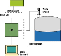
The old adage, "a picture is worth a thousand words" (portrayed in Fig. 2), is being implemented by these IT systems via Ethernet video transmission throughout a plant-level local-area network (LAN) or corporate wide-area network (WAN). This setup effectively brings the off-site engineers to the plant site and provides immediate assistance to the on-site operations staff. Travel can be reduced or eliminated, production delays minimized, and engineering expertise maximized among a network of plant operations.
Figure 2: Every Picture Shares a Story
"A picture is worth a thousand words" aptly describes the use of IT systems via Ethernet to transmit images and data throughout a plant-level LAN or corporate wide-area network WAN.
Not for every occasion
Like other control instrumentation, vision systems do not solve all process needs. For instance, heavy vapor layers over some fluids can obscure the level/wall interface. In these cases, more conventional level instrumentation such as flotation or ultrasonic devices might be better suited to the job.
Vision is also at the high end of the price spectrum, so processes that require less-critical control or do not lend themselves to enhanced analysis and control from visual observation are also better suited to more traditional types of instrumentation.
If you are considering instrumentation for process control, you would be wise to think about the features offered by various types of systems. The lowest-cost answer might not always be the best fit for your current needs if it short changes future expansion needs.
Likewise, upper-end systems can be overkill if their extra capabilities are not exploited fully. What often is overlooked in the analysis of a particular instrument choice are considerations outside the immediate problem's resolution.
Prices for vision systems continue to drop; however, competitive advantages more likely will be derived from the ability of these systems to multiplex more and more camera systems per processor. By doing so, the systems will streamline data gathering and analysis to a single network point for easy distribution throughout the network.
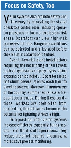
When considering vision technology for your process, do not just assess the impact it can make on increased safety (see the sidebar), throughput and productivity; also consider its ability to convey real-time process video across the enterprise, creating a virtual manufacturing environment.
O'Brien is engineering manager for J.M. Canty Inc., Buffalo, N.Y. Contact him at PaulO@jmcanty. com.
