In economics, “froth” is bad news. It means stock prices are well beyond their actual value and a bubble is about to burst. We deal with a somewhat similar problem in chemical storage. Excessive foaming of liquids impacts storage capacity, taking up precious space and leaving companies with potentially costly remedies.
The accumulation of foam in chemical storage, referred to going forward as “foam inventory,” is the result of foam creation competing with foam decay.
foam inventory = foam creation - foam destruction (decay)
The following sections examine one manufacturer’s struggle with foaming and how the company addressed the issue. Three factors contributed to foam creation in the manufacturer’s system:
- Mechanical work in the centrifugal pump could modify the liquid emulsion feed, likely causing foaming when it contacted air.
- The inlet grating could create foam by mechanical agitation of the liquid as it entered the treater.
- The interaction of the treating liquid and the solid panels to be treated could cause foaming conditions.
One Manufacturer’s Challenge
As part of a final manufacturing step, a manufacturer needed to treat a porous, solid product sold in sheets. The treating vessel was about 10 ft × 100 ft in diameter and originally intended as an autoclave. The horizontal vessel had a head on one end that could swing open and shut with a hinge. While the vessel was rated for high pressure and reasonable temperatures, it barely operated above room temperature, and it faced slightly more pressure than the static head of liquid that would fill it.
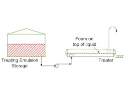
The manufacturer loaded solid sheets on small flatbed rail cars and pushed them into the vessel. The next step was to close and clamp shut the swing-head to the vessel. The centrifugal pump supplied the treating fluid from the tank. After the required treating period, the manufacturer emptied the vessel. The piping configuration allowed the same pump used for filling the treating vessel to return the treating fluid back to its storage tank. Venting of air from the treating vessel was through a long, vertical line to atmosphere. Gratings at the treating vessel prevented large chunks of potentially loose solids from plugging either the liquid line or the vent line. The drum was sealed with liquid by allowing the treating liquid to partially fill the vent line during filling. Figure 1 shows a simplified schematic of the configuration.
Plant capacity was limited by foaming of the treating fluid as the treater was filled. The manufacturer had to drop the filling rate significantly to allow the treater to fill properly. In contrast, foaming was not a significant problem in emptying the liquid from the treater back to the storage tank.
Anti-Foam Options
On the foam destruction side, the only factor in play was normal foam decay. The amount of foam destroyed was related to the residence time of the foam. If the feed rate was too high, the residence time was too short, and foam accumulated.
To avoid excess foaming, the feed rate had to be reduced. When emptying the treater, foam wasn’t normally a problem. The storage tank had a much larger free volume than the treating tank. Additionally, there was no inlet grating in the storage tank and no contact with the material to be treated. These factors led to less foam creation, a higher ability to handle foam, and no foam-induced rate reductions when emptying the treater back to the storage tank.To increase the filling rate, the following, or any combination of them, must be performed: Increase the foam inventory, reduce the foam creation rate, or raise the foam destruction rate. In this particular case, the tolerable foam inventory could not readily be changed. Increasing the treating vessel volume would be cost-prohibitive and difficult to implement.
The Solution
Using anti-foam agents wasn’t an option for the manufacturer because it could not change the required chemistry of the system due to its impact on feed and product qualities. Anti-foam agents, while effective, are costly and would end up in the product. Also, having antifoam in the product sheets would require extensive testing to see if it could be tolerated.
Based on this, the manufacturer decided to focus on reducing the foam-creation rate first by modifying the inlet grating and piping into the treater to reduce foam creation at the inlet grate. Additionally, the manufacturer no longer needed to use the centrifugal pump to fill the treater thanks to the treaters’ original design conditions. Instead, the manufacturer added a vacuum system to pull air out of the treater. After reducing the treater to a low pressure, the treating emulsion storage tank’s valve opened to release the treating solution, driven by pressure differential between the tank and the treater. To save costs while testing the idea, the manufacturer used a rental vacuum system to generate the vacuum.
Operation by using vacuum to transfer the treating emulsion had two major benefits:
- First, it reduced the amount of air in the treater so less oxygen was available to induce foaming.
- Second, it eliminated shearing action in the centrifugal pump that was a precursor step in foam creation.
Overall, the foaming rate dropped dramatically. The project was a success and once it was proven to work a permanent vacuum system was purchased and installed.


