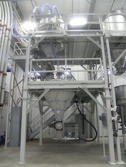
The Dynamics of Pneumatic Conveyors in Chemical Processing: Flow, Control and Reliability
Pneumatic conveyors orchestrate the seamless transfer of diverse bulk materials, from powders and solids to particles and products. They can deliver material across complex routes, seamlessly changing direction when necessary, in an enclosed, dust-free configuration. Yet, engineers and operators often don’t fully understand pneumatic conveyors to take full advantage of system capabilities. Little has been published on the potential of pneumatic conveyors, even though they are simple, flexible and versatile systems.
Pneumatic conveyors use pipes or ducts as transportation lines carrying a mixture of bulk materials. They move bulk solids through the piping by suspending the material in a stream of air or gas over vertical and horizontal distances, up to hundreds of meters.
Bulk materials in the form of fine powders are especially suited to this transfer method, although it’s possible to transport particle sizes up to a centimeter in diameter. For some applications, such as fine-grinding or pulverizing processes, pneumatic conveyors are the only possible means of transport.
A closer look at how pneumatic conveyors operate, including their flow, control and reliability challenges can help operators and engineers gain a better understanding of their advantages and limitations.
Pneumatic Conveyor Basics
A pneumatic conveyor’s essential elements include a motive air source, a feeder or similar bulk material-introduction device, a conveying line, a termination vessel (such as an air-material receiver) and a collection/separation system. The motive air source is also called an air mover. This is a fan set or blower set, often one operating machine and another on standby. The feeder delivers the bulk material via different methods, including airlocks, injectors, screw pumps and special pressure vessels. The bulk material’s physical properties as well as conveying capacity and function influence the configuration and operation of the pneumatic conveyor.
Pneumatic conveyors handle a wide range of capacities, from several kilograms to tens of tons per hour. These conveyors have been designed and manufactured in many different models and materials, such as different grades of carbon steel, stainless steel, alloy steels and others. Moreover, fluctuations in the feed rate resulting in overloading or under-loading will not affect or damage the system. The enclosed nature of a pneumatic conveyor prevents contamination and associated safety and reliability issues. This also prevents contamination of the handled bulk materials and plant environment, avoiding dust generation and allowing the safe transfer of contamination-sensitive bulk materials, including dusty and hazardous materials.
There are four basic types of pneumatic conveyors: pressurized, vacuum, a combination of pressurized and vacuum, and fluidizing.
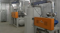
In pressurized or pressure systems (Figure 1), the bulk material is charged into an air or gas stream operated at higher than atmospheric pressures. The velocity of the air stream maintains the solid particles in suspension until it reaches the destination, which could be the consumption point, a processing unit or a separating vessel — usually an air filter, cyclone separator or similar.
Vacuum systems (Figure 2) operate similarly, though they use a system pressure lower than atmospheric pressure. Pressure-vacuum systems combine the features of these two techniques, with a separator and a positive-displacement blower set between the vacuum charge side of the system and the pressure discharge side.
Fluidizing systems operate on the principle of passing air through a porous membrane, which forms the bottom of the conveyor, thus giving finely divided, non-free-flowing bulk solids the characteristics of free-flowing bulk material. This technique is commonly employed in transporting bulk solids over short distances — for instance, from a storage bin to the charge point to a pneumatic conveyor. Fluidizing systems are advantageous because they reduce the required conveying air volume, thereby minimizing power requirements.
In a pneumatic conveyor, the system’s air mover (fan set, blower set or similar) changes the air pressure in the conveying line. Typically, the air mover’s location determines whether it generates pressure or vacuum. A typical pressurized conveyor configuration includes an air mover installed at the start of the pneumatic conveyor. For a vacuum-type conveyor, the air mover is located at the end of the conveyor to create a vacuum in the system. The operation of the air mover would adjust the pressure (positive pressure or vacuum) and the airflow for the conveyor system. This can be done through different methods, and it would provide the needed control for the pneumatic conveyor.
The capacity of a pneumatic conveyor depends on many factors, such as the bulk density, energy within the conveyor and the length and diameter of the conveyor. One advantage of a pneumatic conveyor is the ability to handle a diverse range of bulk materials and solids using a single system. For example, a pneumatic conveyor can manage powders with various bulk characteristics, as well as flakes, pellets, capsules, tablets and other friable materials. The flexibility of the system allows for the transportation of multiple ingredients.
Simple, Cost Effective and Versatile
Some engineers may think pneumatic conveyors are complex or expensive. But the opposite is true. These conveyors are very flexible, cost-effective and versatile. The pathway of the pneumatic conveyor can be decided based on existing obstacles and available opportunities, for instance, bypassing installed equipment and facilities or using existing openings in structures, such as walls, roofs and floors. They are easy to integrate into plants, processing units and production environments where machinery, equipment and other obstacles often exist. They also occupy minimal floor space.
Pneumatic conveyors typically have fewer moving parts than conventional mechanical conveyors, such as belt or screw conveyors. Pneumatic conveyors are more straightforward, more reliable, more compact, and lighter than many other conveyor types. A pneumatic conveyor uses a basic, small-diameter pipeline to transfer bulk materials. Designers can arrange the pipeline with bends to fit around existing equipment, giving the system more layout flexibility.
Dilute Phase vs. Dense Phase Conveyors
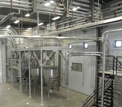
Pneumatic conveyors fall into two classifications: dilute phase (Figure 3) and dense phase (Figure 4). Either one can run under pressure or vacuum. As a rule of thumb, dense-phase types are usually suitable for fine-grained powders, and dilute-phase systems handle coarse-grained, granular materials.
Dilute-phase conveyors. These systems move bulk materials that are suspended in an air stream from the positive pressure of a blower or fan set upstream of bulk material intake points (in pressurized versions) or by a vacuum pump that removes air from the system downstream of bulk material discharge points.
The faster the air/gas velocity, the more bulk material moves. As the airspeed picks up, larger particles become entrained and moved. The start point where the conveyor picks up speed is generally considered the system’s most critical area. Because the bulk material drops from a static state to the airstream below, it should immediately become entrained.
The airstream velocity is also a critical parameter because there is a minimum speed that bulk materials are picked up and entrained at the feed point. The airspeed required to pick up the bulk material depends on each particle’s size and density but can range from 16 m/s to 40 m/s. Obviously, a portion of the energy the air mover provides is consumed for the frictional loss. Higher speeds mean higher frictional losses.
A dilute-phase conveyor usually operates at a relatively high velocity at a low-pressure differential. The ambient air temperature, humidity and altitude can affect the operation of a dilute-phase pneumatic conveyor.
Dense-phase conveyors. A dense-phase pneumatic conveyor (Figure 4) transports particles at a high pressure and low velocity but does not suspend particles in the conveying air. This method is suitable for gently moving fragile or abrasive materials with particles 18 mm and smaller over long distances, typically more than 50 m. It can handle materials such as different sands, feldspar, ashes, glass cullet, alumina, glass batch mix, carbon black, resins and beans. The system conveys material at a relatively low speed to reduce materials degradation, air consumption, and abrasion on the pipeline, bend and diverter contact surfaces.
This system also can stop or start with the conveying line full of bulk material. In many cases, operators load the system and process the material in batches. In this instance, operators load the bulk material into a special pressure vessel called a blow pot or transporter. When the vessel is full, the material inlet and vent valves close and compressed air enters. The compressed air extrudes the bulk material from the pressure vessel into the conveyor line and to the destination. Once the vessel and conveying line are empty, the compressed air shuts off, and the vessel is ready for reloading. This cycle continues on a batch-type basis.
To overcome resistance in the conveyor line over a long distance, supplementary air injectors (also called air boosters or air assists) can be placed along the conveying line. These injectors provide additional air to help maintain conveying velocity, transfer bulk materials over long distances and minimize line plugging. Operators also can use them to gently restart flow when bulk materials remain in the line after the conveying cycle. It’s also important that operators use an air injector with a high-pressure manifold to prevent back-feeding of bulk material into the compressed air system.
Dense-phase vacuum conveying is also appropriate for gently conveying fragile or abrasive bulk materials in short distances, typically 40 m or less. This system is suitable for transferring powder and granules at a medium/low rate (20 tons per hour or less) in applications such as unloading systems. A less commonly used semi-dense phase conveyor configuration uses a pressure vessel with a fluidizing bottom to handle semi-abrasive powders and fluidizable powders that need aeration to discharge into a conveyor line. Better options exist for fragile bulk materials or bulk materials containing large, variable or both large and variable particle sizes. As a rule of thumb, the largest particles handled by this method are approximately 6 mm.
Limitations and Challenges of Pneumatic Conveyors
A typical pneumatic conveyor requires more energy to operate compared to other types of bulk material conveyors. Therefore, pneumatic conveyors need more installed power and consume more electricity to move a certain amount of bulk material. Pneumatic conveyors are not considered energy efficient because of the amount of energy required to create positive air pressure (or vacuum) and the associated frictional losses.
In fact, in applications with the same transfer rate over the same conveying distance, a pneumatic conveyor can require two to eight times the horsepower of a mechanical conveyor. A pneumatic conveyor usually requires a more complicated collection system than a mechanical conveyor because the pneumatic system has to separate the conveyed bulk material from the conveying air/gas at the system’s end.
There have been some limits on differential pressures. As a very rough indication, the maximum conveying pressure is around 6–7 Bar for pressure systems and 0.5–0.7 Bar for vacuum systems; however, some applications have used pressures beyond this limit successfully.
Some bulk materials have characteristics that make them difficult to convey in a pneumatic system. Examples include a bulk material with a large particle size and high bulk density and an extremely sticky bulk material, which tends to build a coating on any material-contact surface. In a pneumatic system, such buildup often leads to total pipeline blockage. These difficult materials can be easier to transfer in a mechanical conveyor that’s been carefully chosen to handle them.
Particle degradation is a reported problem. For many applications, such degradation has no effect at all, but for some this is a critical issue. Prediction of degradation levels for any given pneumatic conveyor and conveyed bulk material represents a significant challenge. Particle degradation can occur in many ways, including pipeline wall collisions in both bends and straight sections, particle-to-particle collision and degradation specific to the conveyor feeder, such as a screw feeder or rotary valve. Dealing with such a problem has always proved complex.
The issues raised by particle degradation include increased bulk material dustiness, changes in bulk material handling characteristics and changes in material appearance. This could lead to poorer bulk materials and a consequent real and perceived reduction in quality. Ultimately, these factors can give rise to problematic operation of downstream systems and a reduction in bulk material value. Experimental and empirical data are keys to solving this challenge.
Final Notes
Pneumatic conveyors offer benefits like operational flexibility but also have downsides, such as capacity limitations and high power consumption. They find common use in applications involving fine powders, primarily in low to medium capacities for specific services and plants. Notably, they are applied in fine-grinding services and pulverizing processes. Proper attention to detail in design, sizing, selection and configuration is crucial for preventing issues and frequent shutdowns. Operational histories would be a good source for the selection and application of pneumatic conveyors, specifically to answer hard questions regarding sizing, configuration, and detail design for a specific application.
References
- “Answers to Eight Common Questions About Pneumatic Conveying,” Nol-Tec Systems Inc., www.nol-tec.com/insights/answers-to-eight-common-questions-about-pneumatic-conveying.
- Bilgihan, Hakan, “PNEUMATI-CON Dilute Phase Pneumatic Conveying Systems,” Conveyormag.com (Sept. 22, 2021), https://conveyormag.com/pneumati-con-dilute-phase-pneumatic-conveying-systems.
- “Common Differences Between Dense Phase Pressure Conveying and Dense Phase Vacuum Conveying,” Nol-Tec Systems Inc., www.nol-tec.com/insights/common-differences-between-dense-phase-pressure-conveying-and-dense-phase-vacuum-conveying
