I was talking to the energy manager at a large oil refinery. I had worked on the design for a crude unit revamp there the previous year. He casually commented, “By the way, they decided to put E-15B in parallel with E-15A.” He paused for a moment when he saw the look on my face. “That doesn’t matter, does it?”
“They did what!?” He was rather shaken by my vehement response.
A key part of the preheat train design was a new shell-and-tube heat exchanger, E-15B, added in a countercurrent series arrangement with an existing heat exchanger, E-15A, to recover additional heat from a major product rundown stream. As discussed in my March 2022 column, (“Squeeze Out the Heat”), this configuration improves the use of temperature differences, thus increasing heat transfer. Unfortunately, during implementation of the revamp project, the construction team found the piping would be simpler if they placed E-15B in parallel with E-15A, so they installed it that way. That change turned out to be significant: It reduced the heat recovery benefit of the revamp by about 50%.
I asked the energy manager if they could correct this error. He was skeptical. The first opportunity to make any changes was several years away, at the next turnaround. Even then, the change would be mechanically difficult; he doubted it would be given priority.
A heat recovery project at a petrochemical complex posed a different problem. This project added a new heat exchanger to preheat deaerator feed water, using heat from a product rundown stream. The project was intended to reduce both the steam demand in the deaerator and the air cooler’s heat load.
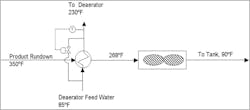
We had to limit the deaerator feed water temperature to 230°F. I recommended a system that bypassed a portion of the rundown stream around the new heat exchanger to control this temperature. However, the project was installed with the bypass on the deaerator feed water instead (see Figure 1).
Figure 1. System designed to bypass a portion of the rundown stream around a new heat exchanger instead was installed with the bypass on the deaerator feed water.
Shortly after the project came online, operators reported the preheated water temperature frequently exceeded the 230°F limit; the pressure drop in the deaerator feed line was excessive due to vapor locking in the heat exchanger. The problem was in the control scheme. Bypassing deaerator feed water around the heat exchanger reduced heat pickup, as expected. However, though the heat pickup decreased, the amount of water passing through the heat exchanger fell even more. Consequently, the temperature of the water leaving the heat exchanger rose as the bypass opened, and often reached its boiling point — hence, the vapor locking. This would not happen with a bypass on the rundown stream.
These projects I designed failed because they were installed incorrectly. The root problem was poor communication, as is so often the case. I have often wondered how many projects have failed because of mistakes in my designs — but I am unaware of any such cases. If you happen to know of any, please don’t tell me about them, and leave me in my blissful ignorance!
For More Information: Alan P. Rossiter, ‘Back to the Basics,’ Hydrocarbon Engineering, Vol. 12, No. 9, pp. 69–73, September 2007.
About the Author

Alan Rossiter
Energy Columnist
Alan Rossiter is a former contributor for Chemical Processing's Energy Saver column. He has more than 35 years of experience in process engineering and management, including eight years in plant technical support, design and research with Imperial Chemical Industries (ICI, United Kingdom) and nine years in energy efficiency and waste minimization consulting with Linnhoff March, before starting his own business. In 2019 he joined the University of Houston as Executive Director, External Relations for UH Energy. He is a chartered engineer (U.K.) and a registered professional engineer in the state of Texas. His latest book, Energy Management and Efficiency for the Process Industries, coauthored with Beth Jones, was published by John Wiley & Sons in 2015. He is a Fellow of the American Institute of Chemical Engineers and a Past Chair of the South Texas Section of the AIChE.

