Processing Equipment: Improve Your Critical Drawings
Crucial details about chemical and hydrocarbon processing facilities reside in piping and instrumentation diagrams (P&IDs). These key drawings contain a wealth of information beyond piping and instrumentation, including equipment, controls, configuration, safety and many other things. However, the look of P&IDs can differ markedly among industries, technology suppliers, engineering contractors, etc. In an effort to align the industry and generate value for its member companies, Process Industry Practices (PIP) has published a practice for how to draw P&IDs.
Process Industry Practices (PIP), Austin, Texas, is a member consortium of process industry owners and engineering construction contractors. Members collaborate to harmonize internal company standards and “best practices” around design, procurement, construction and maintenance into industry-wide PIP practices for member use.
The consortium (see sidebar) was founded by 17 members in 1993 with the shared goal of reducing process facility costs through the development and implementation of common industry practices for design, procurement, construction and maintenance. PIP members now number at approximately 101 active members and 46 non-active members. Active-member-company volunteers have worked to harmonize and maintain over 500 published practices for the process-related industries. Volunteers are split into function teams for specific practices, such as the one for P&IDs, PIC001. The P&ID function team is responsible for the P&ID practice and process-related questions.
PIC001, first published in November 1998, was revised and republished with many updates in 2018. The P&ID revision team consisted of both process engineers and P&ID designers from owner-operators and engineering-construction contractors. The updated practice should help both engineers and designers in all project phases — from engineering feasibility, through operation and during brownfield modifications.
The text of the practice is divided into four sections. The “Formatting” section includes guidance for overall layout and details for drafting, including line weights and font sizes. For example:
• Primary flow shall be shown on each P&ID from left to right (4.2.1.2.1).
• No more than three pieces of major equipment shall be shown on a P&ID to avoid clutter (4.2.1.4).
• Equipment numbers, titles and data for equipment shall be shown within two inches from the top inside borderline of the P&ID, directly above the equipment and on the same horizontal plane as other equipment identification (4.2.4.4).
• Primary process lines drawn vertically shall break for primary process lines drawn horizontally (4.2.3.10).
The practice calls for a standard drawing size of 22 in. × 34 in. All symbols, text sizes and line weights in the practice are based on this drawing size. However, everything remains legible when reduced to 11 in. × 17 in.
The remaining sections — “Equipment,” “Piping” and “Instrumentation” — give direction on how to show those components of the drawing and information to include. For example:
• Equipment shall be shown with simple outline representation (4.3.1.1.2).
• Internals for equipment shall be shown as dashed lines. Details of internals that have no significant bearing on the piping design and layout or equipment operation shall be omitted (4.3.1.6).
• A pump description should include the equipment number, title/service, capacity (flow and total dynamic head), power requirement, materials of construction, and insulation/tracing (4.3.3).
• Line (pipe) sequence numbers shall originate and terminate at equipment, with branches that terminate at different equipment having their own line sequence numbers (4.4.1).
A list of equipment descriptions and what information should be included is provided for nine common classifications of equipment, not just pumps.
Figure 1. A standard set of symbols is used for showing necessary information.
Valuable Appendices
Most users tend to flip immediately to the appendices, which include a lot of useful information, such as legends sheets with lists of abbreviations, line service codes and equipment codes. The appendices also contain a symbol library for pipe, instruments, valves, pipe fittings and equipment; these were expanded in the recent revision to include more solids-handling equipment and safety symbols (safety showers, hydrants, etc.).
The practice includes a standard symbol library in .dwg and .dgn formats. A smart symbol library isn’t yet available but member companies report that creating a basic smart symbol library takes 40–100 hours. The updated practice incorporates better strategies for “smart” P&ID systems but remains completely software neutral. Traditional computer-aided-design programs or an advanced system like SmartPlant P&ID can follow PIC001. The previous revision of PIC001 relied heavily on implied components — i.e., drawing a simple control valve and referencing a detail in the legend sheet to show the position indicators, solenoids, etc. In a database or smart P&ID, showing the components is more critical because the graphics are used to generate lists or for correlating to other programs. So, the updated revision still allows implied components but de-emphasizes that technique.
Appendix D is brand new and contains a complete supplement for hygienic (sanitary, cGMP) processes (food, pharmaceutical, etc.). There is text to supplement the written portion of the practice, additional legend sheets with symbols and abbreviations, as well as hygienic P&ID examples. A few key points from the text include:
• Packaging lines and material flow diagrams shall be laid out relative to the plot plan orientation and sequence of operations. To achieve this, off-page connectors may be positioned vertically (D – 4.2.1.18).
• Additional equipment classifications are provided for filling and packaging, ovens, dryers, etc. (D – 4.3.2).
• A list of equipment descriptions and what information should be included is given for six more common hygienic classifications of equipment (D – 4.3.3).
The appendix contains anything unique to hygienic processes; so those not in hygienic processing can disregard Appendix D entirely. The team has plans to add more appendices with information unique to other industries.
However, no matter how much the practice expands, the goal remains the same — to make P&IDs easy to read for everyone. More-consistent P&IDs among companies will reduce both the time spent on a “learning curve” and the errors made in “translation” or at system interfaces.
Process Flow Diagrams
Within the last five years, the P&ID revision team also noticed a gap in the industry regarding process flow diagrams (PFDs). Like P&IDs, depictions of PFDs vary widely among technology providers, vendors and engineering contractors. However, unlike for P&IDs, no practice or guideline existed. So, the team created a new separate guideline for PFDs — PIE001. This is the first of its kind in the industry.
Like PIC001, PIE001 is meant for both process engineers and process designers. It contains the key parameters for what a PFD must include. A PFD has many uses and PIE001 covers most of them — from something as simple as a block flow diagram to a complex drawing that contains propriety design criteria and equipment sizes.
Very early in the development of the guideline, the team agreed it was essential to include a heat and material balance (H&MB) with a PFD. However, PIE001 leaves several options for how to include the H&MB — e.g., as a separate document with a cross-reference note or on the PFD itself. PIE001 sets guidelines for the minimum information needed for each H&MB stream — temperature; pressure; total flow; state (i.e., gas/liquid/mixed); and mass, molar, or volumetric flow of each component. It’s acceptable to list minor components with one or more major components or in a pseudo-component (i.e., “low boilers” or “C6+”).
Figure 2. Photo taken at the 2019 PIP Annual Conference shows team members (from left to right) back row: Eric Pear, Matt Snyder, Jon Wactor; 3rd row: Judy Krueger, Steve Fortune, J.D. Kim, Rahul Rao; 2nd row: Virginia Mendez, Myrka Escamilla, Alvin Twitchell, Norman Beveridge; and seated: Danny Thai, Julio Lopez, Christina Trotter, Steve Cillessen, Justin Bader.
Like the P&ID practice, this guideline calls for a standard drawing size of 22 in. × 34 in., where everything is legible when reduced to 11 in. × 17 in.
The guideline addresses both batch and continuous processing. If a plant can make multiple products, then each product may require its own PFD. The drafting guidelines (line weights, font sizes) appear in a separate section of the text for ease of use.
It’s worth citing a few other notes of interest:
• Duplicated equipment (e.g., pumps) may be shown by a single symbol if all equipment tag numbers are listed (8.7.6).
• Trayed columns should show at a minimum the top, feed, side draw and bottoms trays (8.7.7).
• Utility streams should originate and end near the piece of equipment (8.9.5).
• Just major primary instrumentation for the process should be shown, as PFDs only are intended to give an overview of the process control philosophy (8.10.1).
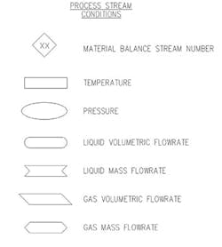
Like PIC001, the guideline’s appendices include a symbol library, a list of common abbreviations and a wide variety of examples. The legend sheet also includes a standard set of symbols for showing process information on PFD streams, e.g., temperature should be shown in a rectangle; Figure 1 depicts the complete set. Using the same stream symbols probably is the simplest step toward greater consistency in PFDs across the industry.
PIC001 and PIE001 differ in one important respect, though. The P&ID document is a “practice” in PIP parlance. It uses strong language like “shall” and is meant to be followed more strictly. The PFD document is a “guideline.” It uses somewhat weaker language like “should” because PFDs have a wider range of uses and requirements. Even with the less strict requirements, PIE001 still should help bring greater consistency to PFDs across the industry. As with other PIP documents, it’s common for companies to add a short overlay, noting any company preferences or adjustments.
Improve Your Drawings
PIP and its P&ID team are excited to bring PIC001 up-to-date with trends in the industry toward smart P&IDs and to introduce PIE001 as a first-of-its-kind guideline for PFDs.
Member companies can find both the practice and guideline on the PIP website, www.pip.org. Non-members also can take advantage of them via subscription.
CHRISTINA TROTTER is a senior project engineer for Burns & McDonnell, Kansas City, Mo. Email her at [email protected].
ACKNOWLEDGEMENTS
The author thanks the entire PIP P&ID function team (Figure 2), especially its previous and current co-leaders — Jay Clark (3M), Julio Lopez (Kiewit) and Steve Cillessen (KBR) — for their contributions to the P&ID and PFD practices.


