A guide to materials and fabrication
This is the second article in a three-part series intended to provide guidance to individuals not versed with specifying welded equipment (e.g., pressure vessels, heat exchangers and tanks). The first part, which appeared in the January 2008 issue. The final part of the series will address design mistakes.
"Twenty-two weeks after receipt of approved drawings.” How often do you see this in a quote and don’t understand why it takes so long to fabricate equipment. With the loss of in-house fabrication-savvy personnel over the last two decades, many owner/operators and engineering companies often write purchase specifications that can add unnecessary time and cost to a project.
So, in this second article in our series, we’ll provide pointers on how to avoid delays and achieve savings in the fabrication process. Moreover, we’ll cover techniques that, if schedules permit, can improve vessel reliability and thus forestall costly repairs down the road.
1. Know your fabricator’s limitations. Nearly all ASME-stamp-holder fabricators are qualified to weld carbon steel and stainless steel; some are qualified for high nickel. But when ordering vessels in an exotic alloy (e.g., titanium, tantalum or zirconium), another niche material (e.g., copper, aluminum or chrome-molys), or made via a specialized process (such as clad overlays), do your homework. Welding is a skill and all metals don’t weld in the same manner or require the same skill level to produce a quality weld. If a welder hasn’t used a specific welding process in the last six months, the ASME Code requires the welder to requalify. Therefore, strive to find fabricators that regularly weld the material you need. Call around before making your bidders’ list and request references or a rundown on recently fabricated equipment. This will eliminate “no bids” and less qualified fabricators.
Additionally, it’s a mistake to view a heat exchanger as just another vessel. Heat exchangers are “performance” vessels and “mechanical only” fabricators don’t have the necessary thermal performance software to appropriately analyze your process data to provide an optimum design. It may seem safe to award mechanical only fabricators “replace in kind” orders without performing a new thermal analysis but you may have missed an opportunity to improve your plant’s performance. Also, heat exchanger fabrication requires special processes such as tube-to-tubesheet welding and tube rolling, which depend upon acquired skills and knowledge. So, fabrication should be left to those companies well versed in manufacturing and analyzing heat exchangers.
2. Be aware of wide loads. A wide load is a generic term for over-the-road shipments whose width exceeds 8 ft. or height exceeds 13.5 ft. (Length and weight restrictions also apply.) Western U.S. states have a legal height limit of 14 ft. When exceeding these limits, state (and sometimes city) “wide load” permits must be obtained — requirements vary by state — and driving restrictions such as dawn-to-dusk curfews are imposed. It’s always easier to obtain permits for excess width; states usually require at least one escort vehicle. When height limits are exceeded, utility company involvement and police escort become the rule rather than the exception.
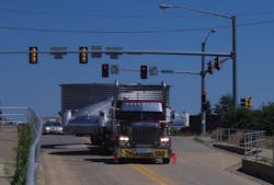
Shipping arrangements are handled by the fabricator but it’s useful to know where the break points are for permits when developing your design. In general, a vessel 12-ft. diameter (or less) can be shipped with minimal permitting and attendant costs. This accounts for the deck height of a trailer and can mean the trailer must occasionally bypass an overpass. For larger diameters, the permit process gets more involved. A “stick trip” (travel of the entire route by a vehicle with a mounted stick to verify clearance prior to actual shipment) often is involved and the design of the equipment (i.e., location of nozzles and other external attachments) will impact the permit. If possible, orient attachments to minimize the load height. Purchase vessels of this size and magnitude from fabricators knowledgeable about handling wide loads. Experienced personnel will recognize if a vessel can be shipped in large sections (Figure 1) and then welded together and tested in the field.
As the vessel’s diameter, weight or length increase, shipping costs can become an overriding factor on which fabricators you invite to bid. Vessels more than 16-ft. diameter can only be trucked a short distance economically; hauling by either rail, barge, or shop fabricated in pieces and field assembled becomes the norm. Between 12-ft. and 16-ft diameters, it becomes very situational, so chose your bidders wisely. Moving a large vessel from the fabricator’s shop through a city to a major interstate or river can cost $10,000/mile and usually the most direct route can’t be taken. Factor in geographic location. It’s easier to ship wide loads in Western U.S. states than in the more congested Northeast.
3. Move carefully with used and relocated vessels. Several suppliers specialize in used equipment; check the classified ads in Chemical Processing and other magazines. Such vessels can be purchased at a discount and are available for your inspection if desired. Also, some operating companies often consolidate operations into a single location, which can lead to relocating vessels and other major equipment across state lines. When relocating a used ASME-code vessel to your state, first check with the office of the Chief Boiler Inspector in your state capital. Many state laws require pre-approval and inspection by that office before a vessel can enter the state. Failure to comply with state law carries monetary penalties.
4. Pay attention to internal coils. Internal coils can be included as part of an ASME vessel but aren’t required to be code stamped. It’s good practice to include internal coils in the pressure vessel scope so that strict quality control procedures are followed and third party inspections are performed. Internal coil failure can lead to forced shutdown, off-spec product quality and possibly safety concerns.
For internal coils, specify butt-type joints with 100% radiography and avoid internal flanges, threads, couplings and socket-type joints. Fillet welds, which are associated with socket joints, are more prone to fatigue failures and aren’t easily radiographed. Return bends (180 deg.) and coils bent from pipe improve reliability by minimizing internal welds and fittings, which are the primary cause of coil failure. A heavy corrosion allowance is suggested. A coil will be buoyant if steam is used as a heating medium (because its specific gravity is less than that of the product); so, design for both hold-down and thermal growth.
5. Understand the role of code inspectors. Vessel inspections are performed in the shop by Code Authorized Inspectors, commonly referred to as AIs. They aren’t employed by the fabricator or vessel owner but by the fabricator’s insurance company or, sometimes, by the local jurisdiction (i.e., state or city government). Their purpose is to confirm vessel safety — not absolute quality — by ensuring the fabricator has followed the rules and procedures of the ASME code. They check to ensure the materials, welding and testing meet the rules of the code for which the vessel was designed and major dimensions, such as vessel diameter and overall length.
It’s up to the owner or designer to perform quality checks. AIs don’t check for all nozzle locations or measure support lug location or many of the minor dimensional requirements (e.g., nozzle projection) needed for your project. They don’t check for special surface finishes, internal or external coatings or contractual requirements written in requisitions and purchase orders. They will check for special testing and examination requirements if specified on the fabrication drawings. If dimensional accuracy or special coatings and finishes are essential for your project, it behooves you to schedule shop inspections.
6. Address documentation and archiving. How many times have you needed to replace a 20-plus-year-old vessel and worried about finding adequate documentation in the company files? Often only a drawing can be located; the code calculation, material certifications and testing records are long gone. The good news is that a vessel’s drawing is enough for a fabricator to provide you with an adequate bid — keep in mind, though, many of the fabrication practices and materials of the past are now obsolete. If documentation can’t be found, there are alternatives you can explore in lieu of starting from scratch.
Perhaps the original fabricator still has the print. For ASME-stamped equipment, fabricators are required to retain what’s called the “Manufacturer’s Data Package” for five years, though many will hold on to this information much longer. However, over the last 20-plus years, substantial consolidation and attrition have reshaped the vessel industry. So, while it’s worth trying, realistically you may find recovering information this way futile.
Your last chance for digging up old information is contacting the National Board in Columbus, Ohio. Besides training and accrediting code inspectors and auditing code stamp holders, it stores decades of manufacturers’ data reports (U-1 forms). A data report is much like the birth certificate of the vessel; it provides a wealth of information, such as major dimensions, materials of construction, shell and head thicknesses, nozzle construction, radiography and hydrotest pressure. To find out if the U-1 form is available, first check the vessel’s code nameplate in the field. If there’s a NB number stamped on it (or on the drawing), simply call the National Board, provide this number and the manufacturer’s name, and within days, for a nominal fee (i.e., $20 to $50), you’ll have the data form faxed to you. (Same day service is available for a small additional fee.)
Such difficulties teach an important lesson. Be sure when purchasing vessels to include any special information (e.g., company purchase order, equipment number, special heat treatment or nondestructive evaluation) somewhere on the drawing because 20-plus years from now, a drawing may be all your successor is able to locate. Also, register and archive your vessel with the National Board — most states require registration [1], but it’s good practice even where not mandated. The cost is typically less than $50 and your fabricator will handle the registration.
7. More (radiography) is less (metal). The continuing climb in alloy prices necessitates a paradigm shift in thinking. It’s becoming more economical to specify more radiography (i.e., X-raying), not so much for joint quality but to reduce wall thicknesses.
Vessel data sheets require the engineer to specify the amount of radiography required for the service. Typically the choices are “full,” “spot” or “none.” This tells the fabricator how much X-raying it should estimate for the job but, more importantly, it affects the required shell and head thicknesses based on ASME code rules. The ASME Code recognizes two types of “full” radiography, RT-1 and RT-2. RT-2 vessels provide the best balance in terms of risk and design economy [2].
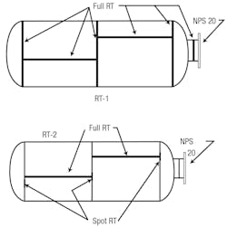
“Full radiography” indicates to the fabricator that “all” pressure-retaining butt joints in the main vessel (excluding small diameter and thin wall nozzles) are to be X-rayed. This can be costly but actually can provide substantial savings when fabricating vessels from expensive materials by avoiding any penalty in vessel shell/head thickness. In ASME Code terms, this amount of X-raying is referred to as “RT-1” (Figure 2) and is stamped as such on the code nameplate.
Full radiography often is confused with 100% radiography, with the later requiring X-raying of all butt welds, including small diameter and thin wall nozzles. Lethal services require 100% radiography. A savvy designer knows the difference and may specify 100% in non-lethal services where process reliability is crucial (e.g., continuous processes vs. batch) or where accessibility to certain joints will be restricted and hamper future repairs (e.g., jacketed designs).
“Spot radiography” is a common choice in the chemical industry for normal service fluids. It involves a 6-in. shot for every 50-ft. of weld seam at locations specified in the code and incurs only a slight, 15%, wall thickness penalty. ASME designates this as “RT-3.” On small and low hazard vessels, often no radiography or “none” is specified; this will increase the wall thickness another 15% (i.e., 30% thicker than for full X-ray).
RT-2, which is a hybrid between RT-1 and RT-3, seldom is specified by owners but offers economic advantages by permitting thinner wall vessels (Table 1). All long seams are fully X-rayed (similar to RT-1) and the longer circumferential seams are only spot X-rayed (similar to RT-3) with one extra quality shot at the T-junctions (Figure 2). Why RT-2? The long seam is stressed two times higher than circumferential seams for most vessels where wind load doesn’t govern design (i.e., vessels under 50-ft. tall). So, have your fabricator quote an optional price for RT-2 on vessels constructed of alloy materials. A vessel engineer can work you through the rules.
In summary, full radiography was once considered only necessary for vessels containing highly hazardous processes or requiring maximum reliability. However, with the ever increasing cost of alloys, consider specifying RT-2 radiography for all welded equipment as a potential way to achieve material/fabrication cost savings.
8. Release the head for fabrication ASAP. Often, the first thing fabricators do when they get the go-ahead to begin fabrication is to order the heads. The design pressure, temperature, vessel diameter, material of construction, and amount of radiography are all that are needed to release the heads for forming. The fabricator usually will wait until the heads arrive (two-to-four weeks later) and check for dimensional accuracy before rolling the shell. So, to ensure the project remains on schedule, don’t delay releasing the heads while you’re finalizing nozzle sizes and locations. A few major fabricators have the equipment to form their own heads. Knowing this ahead of time can be helpful if the project is schedule driven.
9. Get anchor bolt templates. Templates supplied by the fabricator, cut to match the equipment’s actual anchor bolt pattern, can be very useful to your on-site construction contractor when project field schedules are tight. In these situations, concrete pads with anchor bolts often are poured and pre-set before the vessel arrives. If time allows, a contractor may wait for the vessel to accurately determine exact anchor bolt locations before pouring the pad. However, this has obvious time and cost consequences (e.g., crane rental). So, when warranted, have the fabricator provide (with the vessel or ahead of time) a ¼-in.-thick metal or wood template of the vessel’s actual anchor bolt circle pattern. As bolt circles get larger, base rings become thicker and the ability to correct out-of-tolerance bolt patterns becomes more difficult. Small diameter vessels with welded-on legs are just as susceptible to arriving with unacceptable tolerance deviations because they are mounted independent of each other.
10. Opt for dual stamping. The code allows vessels to be dual stamped (i.e., separate code nameplates for two sets of design pressure and temperature). Pilot plant vessels also are good candidates because they potentially may handle an endless number of products/processes. The drawback to dual stamping is if both stamped pressures are over 15 psig, then the vessel then would require over-pressure protection, i.e., two separate pressure-relieving devices — but this inconvenience can be minimized by installing a three-way full-port selector valve. It’s possible to add a second nameplate after the equipment has been placed in service by “R-Stamping,” but all the code requirements must be met for the alternative design conditions.
11. Insist on a mechanical guarantee. Fabricators aren’t responsible for classifying a vessel for lethal service, selecting materials of construction or determining corrosion allowances. Nor are they required to provide you with a vessel free from imperfections. They merely need to follow the ASME Code rules and perform the necessary calculations, inspections and tests. The vessel you get won’t be perfect. Therefore, add language in the purchase order requiring a limited mechanical guarantee. Fabricators won’t agree to a lifetime guarantee but will accept one for a set period to repair failures due to mechanical workmanship not caused by neglect or mis-operation. A common term is 18 months after receiving the vessel or 12 months after placing it in service, whichever comes first. Insist that any repair performed resets the 12-month clock.
If the vessel maker completely overlooks a fabrication requirement listed in the specification that affects reliability, then push for a longer service guarantee, such as five years, for the missed item (e.g., rounded corners on pads that cause stress risers and can lead to premature fatigue cracking). You are in an excellent negotiating position once a vessel is fabricated with a design specification error and final payment is pending.
The last part of this series will delve into design issues, such as choosing the appropriate pressure and temperature, head and jacket choices, and how to design a rectangular tank.
Chip Eskridge is technology manager -- mechanical/metallurgy with Worley. He also serves as chairman of ASME B31.3 Process Piping Code. Mike James is a senior consultant, materials engineering, for DuPont, Houston. Steve Zoller is director of fabricated equipment for Enerfab, Cincinnati. Reach them via e-mail at [email protected], [email protected] and [email protected].


