Preclude the Pitfalls of Pump Piping
The pitfalls of centrifugal pump piping are many and varied. However, the main difficulty is that a poor piping layout places the cause of many pump failures outside the physical confines of the pump itself. This makes detection tough for the unwary and inexperienced. Adding to the difficulty, accessible information on the topic of pump-piping design is scarce, and what little is available usually is ignored when a new pump is being installed.
The result of all this is that most pumps are piped incorrectly, resulting in repetitive failures that go unexplained and unresolved. In fact, the way some pumps are installed resembles a "plumber's nightmare." Many pumps are squeezed into a corner and the pipes are threaded in and out without any consideration for fluid flow patterns.
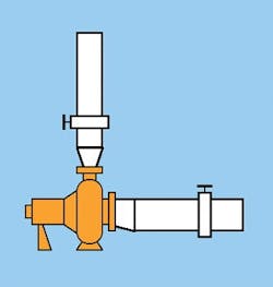
Figure 1:
Positioning the reducer with the flat side on top eliminates the potential problem of air pockets at a high point in the suction line.
Many who read this article will realize to their horror that some of the most problematic pumps in their plants don't follow any of the basic rules of pump piping. Why is this?
To answer that question, let's consider what normally happens when we are about to install a pump in a new system. Where do we go for information about how to arrange the pump piping? Most of us would refer to the pump manufacturer's Installation, Operation and Maintenance (IOM) Manual. Unfortunately, that won't provide a lot of information, because most pump makers have restricted their responsibility to the confines of the suction and discharge nozzles of the pump. Although this attitude is fast disappearing, the change has not yet reached most IOM manuals. As a consequence, accurate and complete information is still severely limited. A high proportion of pumps are installed with inappropriate piping arrangements that result in premature failure.
In spite of this, you can easily avoid the common pitfalls of pump piping by following seven straightforward rules.
Rule No. 1
Position the pump in an accessible location. When laying out the system, give some consideration to the people who eventually will have to look after the pump. Wherever possible, locate pumps in an area with ample space around the pump to provide easy access and working room for routine maintenance. Also, make sure overhead space is adequate for lifting devices and working clearance.
Painful practical experience has shown that if the pump is not easily accessible, it will not get the routine care and attention required to ensure its reliability. What should be a simple matter of checking the running temperature of the bearing housing can often become an unwilling exploration into the depths of a piping jungle. Even keeping the unit clean to facilitate inspection can become an unmanageable chore.
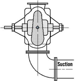
Figure 2:
This configuration introduces uneven flows into the opposing eyes of the impeller, upsetting the hydraulic balance of the rotating element.
Rule No. 2
Make the pipe diameter on both the inlet and the outlet sides of the pump at least one size larger than the nozzle itself. On the horizontal inlet side, an eccentric reducer is required to decrease the size of the pipe from the suction line to the inlet nozzle. Positioning the reducer with the flat side on top, as shown in Figure 1, eliminates the potential problem of air pockets at a high point in the suction line.
A concentric increaser should be bolted directly to the vertical discharge flange prior to the location of any valves. This increaser will slow down the velocity of the liquid leaving the pump to an acceptable rate within the system itself and, in particular, through the check valve and isolating valve. Keeping the velocity low (usually less than 10 ft/sec) reduces friction losses in the line and power draw at the pump.
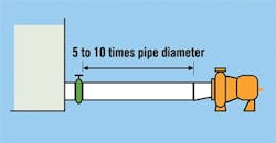
Figure 3:
An adequate straight length of piping provides uniform flow of liquid to the eye of the impeller and the optimum suction condition.
Rule No. 3
Eliminate elbows mounted on the inlet nozzle of the pump. Much discussion has taken place about the acceptable configuration of an elbow on the suction flange of a pump. Let's simplify it: There isn't one!
There always is an uneven flow in an elbow. Installing an elbow on the suction of any pump introduces that uneven flow into the eye of the impeller. This can create turbulence and air entrainment, which can result in impeller damage, vibration and premature pump failure.
The problem is compounded when the elbow is installed in a horizontal plane on the inlet of a horizontal double-suction pump, as shown in Figure 2. This configuration introduces uneven flows into the opposing eyes of the impeller, essentially destroying the hydraulic balance of the rotating element.
Under these conditions, the overloaded bearing will fail prematurely and regularly if the pump is packed. However, if the pump is fitted with a mechanical seal, the seal usually will fail instead of the bearing -- but just as regularly and, often, more frequently. When it is absolutely essential to position an elbow on the inlet of a double suction pump, it must be located at right angles to the shaft.
The only thing worse than one elbow on the suction of a pump is two elbows on the suction -- particularly if they are positioned close together in planes at right angles to each other. This creates a spinning effect in the liquid that is carried into the impeller and causes turbulence, inefficiency and vibration.
Rule No. 4
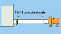
Provide the suction side with a straight run of pipe, in a length equivalent to five to 10 times the diameter of that pipe, between the suction reducer and the first obstruction in the line. For reliable pump operation, liquid must arrive at the impeller eye with the right pressure and smooth uniform flow. Achieving this depends a great deal upon the suction piping design. The arrangement shown in Figure 3 will ensure the delivery of a uniform flow of liquid to the eye of the impeller and provide that optimum suction condition.
Note that this layout contradicts the information given in most IOM manuals that the suction piping should be "as short as possible." This arrangement also supports Rule No. 1 and should eliminate the practice of squeezing the pump into a corner without any consideration for fluid flow patterns or physical accessibility.
The same things apply to package systems, where the focus tends to be on getting as much equipment into as small a space as possible with little regard for piping design.
Rule No. 5
Remove the potential for vortices or air entrainment in the suction source. Eliminate all piping configurations that might introduce an air pocket into the suction side of the pump. These air pockets can create turbulence and air entrainment, which can result in impeller damage and vibration.
If a pump is taking its suction from a sump or tank, the formation of vortices can draw air into the suction line. This usually can be prevented by providing a sufficient level of liquid over the suction opening. A bell-mouth design on the opening will reduce the amount of submergence necessary. This submergence is completely independent of the net positive suction head required by the pump.
Take great care in the design of a sump to ensure that any liquid emptying into the sump does so in such a manner that air entrained in the inflow does not pass into the suction opening. Any problem of this nature may require a change in the relative positions of the inflow and outlet if the sump is large enough or necessitates the use of baffles.
Rule No. 6
Arrange the piping so it imposes no strain on the pump casing. Accurately align piping flanges before the bolts are tightened and independently support all piping, valves and associated fittings. Building the piping from the pump to the system can help reduce pipe strain. Any stresses imposed on the pump casing by the piping decrease the probability of satisfactory reliability and performance.
Laser pipe-alignment tools offer significant benefits. Mounted on the pump or the piping, such tools can provide an effective way to prevent pipe strain during initial installation, which is exactly the right time to stop it.
The effects of pipe strain in a conventional process pump can also be transmitted to the shaft coupling. With the accuracy of laser alignment technology, pipe strain can be measured and should be integrated into the shaft alignment program. By loosening the pipe connection after a correct shaft alignment has been performed, any movement at the coupling will indicate the existence of pipe strain and can therefore be corrected.
However, there is an exception to this rule. The American Petroleum Institute (API) 610 Pump Specification identifies a maximum level of forces and moments that may be imposed on the pump flanges. So, any pump being sold in the petroleum or a related industry must comply with that specification. As a consequence, all API pumps are of a much more robust and heavier design than their ANSI size equivalents.
In high-temperature applications, some piping misalignment is inevitable because of thermal growth during the operating cycle. So, thermal expansion joints often are used to avoid transmitting any piping strains to the pump. However, if the end of the expansion joint closest to the pump is not anchored securely, the pipe strain is passed through to the pump, thus defeating the objective of the expansion joint.
Rule No. 7
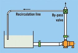
When operating at consistently low flows, use a constant bypass line. If prolonged periods of low flow operation are expected due to variable system demand, install a bypass valve to regulate the flow through the pump. It may also prevent an excessive number of pump stops and starts, which is particularly important with larger motor drivers.
Direct the excess flow back to the suction source of the pump -- not to the suction of the pump -- otherwise, excessive line turbulence may result.
Don't disregard piping
Piping design is one area in which basic principles are frequently ignored, resulting in problems such as hydraulic instabilities in the impeller, which translate into additional shaft loading, higher vibration levels and premature failure of the seal or bearings. Because many factors can contribute to pump vibration and seal and bearing failure, the trouble rarely is traced to incorrect piping.
Some may argue that since many pumps are piped incorrectly, yet operate satisfactorily, piping procedure is not important. However, that doesn't make questionable piping practice correct; it merely makes getting by with it a matter of luck.
Any piping mistakes on the discharge side of a pump frequently can be accommodated by increasing the performance of that pump. Problems on the suction side, however, can cause repetitive failures, which may never be traced back to that area and could continue undetected for many years to come.
Ross Mackay has more than 40 years of experience in the pump industry, and now specializes in consulting and training to improve the economics and reliability of pump installations. Call him at (800) 465-6260.
