Hydraulic systems find wide and varied use at process plants — because they offer an efficient and cost-effective way to create movement and do work. These hydraulic systems must provide high performance, robustness, reliability and availability. However, the design, purchase and operation of hydraulic units usually pose challenges.
A vast array of pre-manufactured hydraulic devices and actuators are available. Configuring systems with these components nearly always requires contending with budget, space, weight and other constraints. Success usually hinges on developing a simple and failsafe configuration using reliable components from a reputable source. Here, we’ll look at practical pointers and useful guidelines to deal with challenges and solve design and operational problems.
Hydraulic Pumps
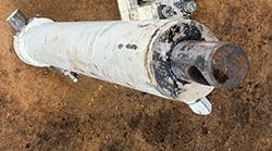
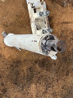
A fixed or variable displacement pump supplies fluid (usually a hydraulic oil) that acts on a component like a cylinder (Figure 1) in the hydraulic circuit to do the assigned work. Typically, a gear, vane or piston pump handles this duty, with the choice depending on operational requirements, performance and budget. Usually, the system should have two pumps, one operating and another on standby.
The cost of electricity or fuel to operate a hydraulic pump set over its entire life span generally exceeds by many times the cost of the pump package itself. Therefore, correct sizing so the pump and driver work most of the time around their best efficiency points is extremely important. Optimum sizing of both the pump and its driver can save a sizable amount of money over the life of the package.
Figure 1. This heavy-duty double-acting unit awaits repair and refurbishment.
First, you must calculate the pressure and flow of the hydraulic system and then select the pump. The torque, speed and power requirements of the hydraulic pump determine the sizing of the driver; this requires finding the maximum torque required at the highest-pressure level of the hydraulic application. Provide enough margin — say, 15–20% — when sizing the pump and its driver.
Electric motors with the same power rating can have different pull-up torques. So, first, calculate the power rating. Then, select a motor based on vendor performance curves that provides the required torque with some margin. The sizing and selection process usually is straightforward because electric motor drivers generally have a starting torque that far exceeds running torque.
Undersizing of hydraulic pumps or their drivers is common. Oversizing poses issues, too, particularly energy waste because the motor operates at below its best (peak) efficiency.
Some hydraulic pumps use engines as drivers. Diesel, gas or gasoline engines have a much flatter torque/speed curve than electric motors; they deliver roughly the same torque at high speed as at low speed. This means an internal combustion engine may develop high enough torque to drive a loaded pump during normal operation but not enough to accelerate it to operating speed (during startup). Consequently, with all other factors being equal, an engine that drives a hydraulic unit requires a higher power rating than that of an electric motor. Sometimes, the power rating of the engine driver is 1.7 times or even more than that of the electric motor. In addition, engines always are more expensive than electric motors and need many other auxiliaries and accessories.
Hydraulic systems nearly always use a pair of positive-displacement pumps. So, a set of relief valves is essential to protect the system against over-pressurization and potentially dangerous failures. These valves also are used to unload the system when starting up a pump or putting one on standby. Vibration and noises can pose challenges and deserve consideration.
Operating Pressure
Most engineers today prefer higher operating pressures (sometimes as high as 400 Barg) for hydraulic piping, cylinders, actuators and devices to achieve compactness, light weight and economic savings. As a very rough indication, increasing the pressure to 200 or 250 Barg from 100 Barg can reduce costs by around 20–35%. However, some systems are better off in the medium-pressure range of 80–150 Barg. Each application usually has an optimum pressure range.
High pressure can require very specific and expensive technologies for devices and pose sealing complications, potential leakage and other problems. In fact, above certain levels, costs may rise with pressure. In general, hydraulic systems with pressures above 350 Barg demand great care.
In high-pressure hydraulic systems, the energy converters fail to transform a portion of the compression energy into useful work. The energy waste mainly causes heating of the hydraulic fluid.
Key Components
Every hydraulic system requires a fluid reservoir or tank. As a rough indication, you should size the reservoir volume to provide 4–10 minutes of pump flow, allowing hydraulic fluid to settle in the tank but recirculate enough for stable temperature and to keep it clean. Also consider hydraulic actuator drain-down and working volume changes. Installing baffle plates in the reservoir to separate return and supply lines enables dirt and air to settle before fluid reuse. In addition, the reservoir needs an air breather/filter to allow fluid volume to change and to filter any incoming air. Suction lines from the reservoir to the pumps demand great attention. Use large-diameter short piping for low fluid velocity. Pumps should have a positive head or be primed before first startup. Putting in a suction filter (suction strainer) isn’t necessarily a good idea. While the filter might improve supply conditions, it can restrict pump supply if not maintained.
Install a pair of pressure filters (one operating, the other on standby) to stop contamination reaching components in the circuit. A cheaper alternative is a filter with a bypass valve. Either way, provide an indicator, such as a differential pressure sensor, to show when the filter element needs replacing.
As already noted, systems generate heat that is absorbed by the hydraulic fluid. This often necessitates coolers to keep the hydraulic fluid within the specified temperature range (whose high limit usually is set to avoid fluid breakdown or damage to seals). The cooling and filtration system comes in one of two general set-ups: an online configuration where the system is installed downstream of the pump set and upstream of the control and actuators; or an offline arrangement where fluid passes through an independent cooling and filtration system and then goes back to the reservoir. (Use of the later system assumes the hydraulic fluid in the reservoir is clean and cool.)
The hydraulic system requires appropriate controls for adjusting pressure and temperature. This calls for suitable instruments, sensors and valves.
Pipe Sizing
For estimating and approximate sizing, the standard flow velocity method of pipe sizing may suffice. However, final sizing of the piping and inline components of a hydraulic system requires a better method.
First, decide upon the overall allowable pressure loss and then distribute pressure losses in different parts of the hydraulic system. Many factors and parameters affect this, making a general rule infeasible. Instead, engineers often must decide what loss is tolerable, based on limitations in heat dissipation as well as requirements to achieve desired work output, system efficiency, overall cost, etc. Of course, the aim is to minimize overall pressure drop; any rise in the pressure drop leads to lower overall efficiency and larger coolers. Many systems can attain a suitable operating temperature range only with a low pressure drop. Performing an optimization can avoid specifying too large piping, hoses and valves, which incur added costs and problems.
Accessories And Auxiliaries
The requirements and specifications of key components and devices of a hydraulic system generate little disagreement. However, no such consensus exists for so-called accessories and auxiliaries, such as isolation valves, which may play an important role in the operation, reliability and maintenance of some hydraulic systems. Isolation valves (usually ball valves) are needed to ease operation, maintenance or future relocation. They can protect personnel during maintenance and stop syphoning of hydraulic fluid when items are changed or removed.
Many hydraulic devices and actuators are sensitive to back pressure. However, adding an isolation (ball) valve usually is acceptable in critical battery limits, provided the installation fittings incur minimum pressure drop and don’t represent a significant restriction or pressure loss to the system.
Overall, the piping and hose length and numbers of fittings are key considerations. Besides suitably sized components, the circuit should have minimum possible length. Use full-bore (full-port) ball valves to reduce pressure drop and equip them with a locking device to prevent accidental closure.
Accumulators usually play an important — indeed, critical — role in many hydraulic systems. Generally, a pair of accumulators are fitted and pre-charged with hydraulic fluid from the pump when operating; they provide backup hydraulic force for transient cases, e.g., a pump shutdown (either deliberate or due to unexpected power loss), changeover from one pump to another, or other reasons. At such times, the accumulators will provide pressurized hydraulic fluid for a short period of time ranging from 15 seconds up to one or two minutes, with the accumulator sized accordingly.
A hydraulic system may include many different auxiliaries and accessories such as a manual drive, manual drive engaging/disengaging system, lock assembly, adjustable limit stops, anti-rotation device, mechanical position indicator, etc.
Central Versus Individual Systems
You can opt either to install a centralized hydraulic system to handle all actuators and devices in a package or unit; or multiple individual and independent hydraulic systems, each to serve one or a few specific services.
A centralized hydraulic system often can offer clear benefits such as higher efficiency and easier handling of peak fluctuations. However, selecting optimum pressure is critical, and sizing of all items assumes considerable importance because different devices and subsystems can affect each other. In addition, when the distances are long and the system contains many different actuators, subsystems and consumers, you should consider all the extra costs, challenges and inconveniences a centralized system may incur.
For instance, the hydraulic fluid may travel through long lengths of piping with many bends. This impacts costs, system rigidity and overall reliability — and may lead to considerable energy loss. However, the larger piping surface area helps dissipate the heat generated by the losses, which sometimes is a positive point.
On the other hand, individual hydraulic systems may offer flexibility and other benefits.
No general rule exists for making the choice between central or individual configurations. You must evaluate your specific system to decide.
Maintenance And Operation
Contaminated hydraulic oil is the bane of hydraulic systems. Indeed, contamination and dirt likely account for more than 75% of all problems and failures in such systems. So, cleanliness is of paramount importance when installing and maintaining components and items.
Pay particular attention to the first hours and days of operation. Change the initial set of oil filter cartridges soon, say, approximately 24–60 hours after the startup. Then, you usually should swap out the filters every 500–1,500 hours of operation. Most of the time, the first charge of hydraulic oil should get replaced fairly soon, say, approximately 100–400 hours after the startup. Subsequent hydraulic oil changes then should occur every 2,000–4,000 hours of operation.
The state of the hydraulic oil is a good indicator of the hydraulic system’s health. Therefore, you always should perform routine sampling and oil analysis. Obtain an oil sample at every filter change and compare it with the previous samples to detect any changes. Monitoring hydraulic oil characteristics and contamination provides a powerful way to pre-empt operational problems and reliability issues.
AMIN ALMASI is a mechanical consultant based in Sydney, Australia. Email him at [email protected].


