Pressure demands in pumped liquid systems come from dynamic and static sources. Friction in the system causes the dynamic losses. For Newtonian fluids, these losses are proportional to the square of the velocity in the system. If flow rate doubles, dynamic pressure drop increases by a factor of four. Static head changes stem from elevation differences or pressure differential between the source and the destination reservoir — and vary with system levels or pressures, not with flowrate. We can simplify the overall terminology to a dynamic pressure change (varying with flow) and a head pressure change (varying with pressure or elevation).
The specific application determines the relative impact of these two factors. Pressure demand for a pump shifting liquid between two atmospheric tanks with close to identical liquid elevations stems almost completely from friction losses. In contrast, the demand when pumping at a low velocity from the ground to a storage tank at a high elevation comes nearly exclusively from head pressure change. Of course, many systems have both dynamic losses and static head changes.
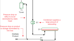
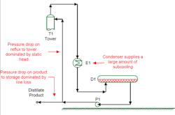
Figure 1 illustrates a system where one pump (P1) sends liquid to two destinations. The pump provides reflux to a distillation tower and also propels the distillate product to storage. Head change dominates pumping the reflux; pressure drop variations due to flow rate changes in the return pipe have very minor impact. On the other hand, pressure demand in pumping the product to storage comes nearly completely from dynamic losses; the liquid elevation in the storage tank has hardly any effect.
Figure 1. Published pump curve indicated unit was controllable at desired rates for providing reflux and sending product to storage.
This system worked without significant problems for many years. However, after a plant expansion, the unit operators complained about difficulty controlling the level in the overhead reflux drum. The source of the problem was interaction of tower performance, changes in dynamic pressure loss for the product, and the head requirements for reflux.
Centrifugal pump discharge head decreases with pump throughput. As the reflux plus product rate rises, discharge head from P1 drops. Pressure requirements on both the reflux line and the product line tightly constrain this system. As the pump discharge head falls toward the pressure requirement for the reflux return, the system works until it reaches a critical limit. This limit slightly exceeds the head requirement imposed by the tower elevation. Because static head dominates the reflux system, if pump discharge head falls even a little below the critical value, reflux rate drops rapidly, even reaching zero in some situations.
The reflux is highly subcooled in this unit. Inside the tower, subcooled reflux condenses rising vapors. If the reflux return rate drops, the vapor rate to the overhead condenser rises. This results in the need to pump even more liquid out of the reflux drum.
Because the product line also tightly constrains the pump, the higher liquid rate can’t be returned to the tower or sent down the product line. The overhead reflux drum fills rapidly.
The operators’ solution to avoid a runaway level in the drum is to ensure the tower always has enough reflux. As needed, the operators turn the level controller on the drum off, setting the overhead product rate in manual. This keeps the pump flow rate down (and head up).
But where does the liquid product go? The operators allow the drum level to rise when suppressing the product rate. Eventually, upstream changes enable a lower reflux rate and a drop in drum level while staying within the pump’s capacity. That capacity is so tight that for at least 30% of the time the operators are running the drum level on manual to prevent a runaway drum level.
Calculations showed the unit should be tight — but still controllable at the desired rates. This assumed the pump would operate on its specification pump curve. However, many pumps in service for long periods don’t operate exactly on their pump curve. With standard maintenance, plants should expect dynamic heads from centrifugal pumps to vary by as much as 5% from published pump curves. In this situation, 5% changed a pump at the limit to one that really couldn’t perform the job.
So, don’t presume that future pump performance will match the published curve. Check what a 5% drop in head would do for every destination to which that pump sends liquid.


