Mixers: Don’t Let Baffles Baffle You
Baffles are internals, generally flat plates, used in agitated vessels to optimize and stabilize the mixing flow pattern and minimize variation in agitator power draw. Baffle recommendations are part of the agitator vendor’s scope although the baffles are designed and fabricated by others. Proper baffle implementation dramatically impacts process results.
Low viscosity fluids in agitated vessels without baffles swirl and have surface vortices with little top-to-bottom vessel turnover. Velocity gradients are minimal. Particle tracing within a horizontal plane shows circular motion almost like the horses on a carousel — rotation but not interaction. Particle traces in a vertical plane show minimal motion, a poor configuration for blending or solid suspension.
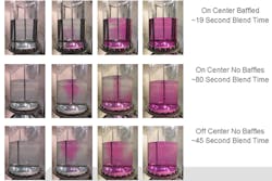
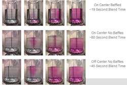
As Figure 1 illustrates, baffles provide advantages with such fluids. Baffles establish an axial flow pattern, minimizing the tangential or swirl component imparted by the rotation of mixing impellers. The baffled flow pattern facilitates top-to-bottom bulk motion, increasing the velocity across heat transfer surfaces and facilitating blending and solid suspension. However, top entry on-center-mounted agitators on a properly baffled vessel draw more power than on an unbaffled vessel because the impeller pumps more fluid in a given amount of time.
Figure 1. Use of baffles dramatically decreases blend time.
In mass transfer reactions, where power draw is a critical parameter, proper baffling increases impeller power draw and improves blending, which increases the mass transfer capabilities of the mixer.
For vertical cylindrical vessels, “standard” baffles — defined as four flat plates of 1/12 vessel diameter, installed radially along the vessel straight side and spaced at 90° — are common for top entry agitators mounted on center. They are recommended based upon “standard” assumptions about the agitator, vessel, fluids and mixing requirements. Many processes frequently deviate from these assumptions! We will discuss frequently encountered deviations.
[callToAction ]
A common misconception is that the number of baffles must equal the number of impeller blades. This arose from the change in baffle recommendations that occurred when high efficiency impellers came into the market, replacing many pitched blade turbines. More accurately, the optimum number of baffles is a function of the ability of an impeller to generate axial flow in the process fluids.
When processing low viscosity fluids with high efficiency axial flow impellers, performance differences between three and four equally spaced baffles, are barely discernable. In these fluids, four bladed pitched blade turbines and six bladed radial flow impellers require four baffles.
Baffle Adjustments
Practical considerations or vessel internals often rule out spacing baffles equidistant around the vessel circumference. Redistributing baffles within a few degrees of equal spacing is fine. However, removing a baffle without respacing the remaining baffles is problematic. In other words, it’s much better to have three baffles at 0°, 120° and 240° than three at 0°, 90° and 180°.
When you must reduce the number of baffles, adjustment of baffle width can maintain power draw and facilitate an axial flow pattern. For a low viscosity fluid, an installation with two baffles at widths of 0.1 × vessel diameter will draw approximately the same power as three baffles at 0.062 × vessel diameter.
Figure 2. Standard and triangular baffles offer nearly identical performance with axial flow impellers.
As seen in Figure 1, off-center mounting in an unbaffled vertical cylindrical vessel will create an axial flow pattern and less swirl than an on-center mounting in the unbaffled vessel. For small vessels, an angle mounted agitator, often called a portable agitator, may make sense. These asymmetric options usually are impractical in large mixers from a mechanical design point of view.
The need for sanitary processing or the handling of fluids with a tendency to foul surfaces creates demand for alternative installation locations and baffle designs.
The Lightnin Mixing Technology Laboratory recently studied triangular baffles. Tests using A510 high efficiency axial and Rushton (radial) impellers evaluated power and flow for the same operation in water for unbaffled, standard plate baffle and triangular baffle configurations. As shown in Figure 2, with the axial flow impeller, the performance of the triangular cross-section baffle essentially equals that of the standard plate baffle. However, with the radial impeller, both flow and power draw decline. With both impellers, lack of baffles results in a marked performance decline.
Another study, summarized in a presentation at the Mixing XIII conference of the North American Mixing Forum (NAMF), looked at the power draw of an A310 high efficiency axial flow impeller in water in an off-center unbaffled configuration. As expected, at constant speed, removing the baffles reduced measured power draw approximately 40% [1].
When fouling or contamination between batches is a concern, installing baffles at ⅓ width off-wall promotes flow between the baffles and vessel wall. At higher viscosities, opt for ½ width off-wall.
Canted baffles, angled in the direction of flow, often are used for cleanliness or when the baffles are heat transfer surfaces. The width of the baffle is calculated to provide the recommended radial component. For example, if a 7-in. baffle width is desired, a 45° canted baffle of 10 in. is suggested because the radial component is (sin 45°) × 10 in. = 7 in.
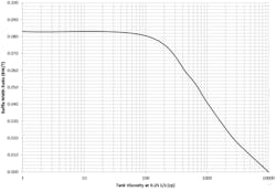
Figure 3. Recommended baffle width depends upon viscosity.
Triangular baffles with a radial component equivalent to the suggested baffle width are nearly as effective as baffle plates for axial impellers. A typical triangular baffle would have a vertex pointing toward the vessel center with a 45° angle made from two plates. To replace a 4-in. baffle with a 45° triangle, the side plates joining at the vertex would each be 4.33 in. The leading face of the baffle is 4 in./sin 67.5°.
Baffles often are helpful when vessels have bottom cones or dishes. Cone bottoms have a small inherent baffling effect. If an impeller is in the cone, use one or two baffles scaled to the cone diameter at the impeller elevation if installation clearances allow.
At power levels above 1 hp/1,000 gal, opt for baffles extending into a dish if an impeller is at or below the vessel tangent line. Without baffles in a dished bottom, an axial impeller at the tangent line exhibits swirl.
With radial flow impellers, particularly in gassed applications, extended baffles are essential for promoting a useful flow pattern to improve gas dispersion.
Raising the position of a lower impeller up into the baffled straight side of a dished or cone bottom vessel can dramatically improve the mixing flow pattern.
Important Factors
Baffle recommendations vary with fluid properties and geometry. Common factors influencing baffle recommendations include:
• solids wet-out;
• higher viscosity or non-Newtonian (e.g., pseudoplastic) fluids;
• unusually high or low power intensities;
• glassed vessels;
• internal coils, jackets, vertical tubes and flat plate heat transfer surfaces;
• rectangular, horizontal or asymmetric vessels;
• side-entry mixers; and
• dip pipes, thermowells, probes and other vessel internals.
Solids wet-out. A common requirement is to add solids at the liquid surface. Solids can take many forms. Some have a tendency to float; others are difficult to wet-out, forming air-filled clumps. Fine solids also may trap air. Typically, the mixer/baffle interaction is designed to facilitate drawdown, either through vortex creation or a recirculation loop.
Usually, when solids must be drawn down, a vortex is created with a down-pumping axial flow impeller and baffles cut off at the height of the impeller. Reference 2 provides general recommendations for impeller submergence and baffle width. Installations with cut-back baffles at 2% of tank diameter have proven more effective than unbaffled ones. Fluctuating liquid levels during solids addition present challenges that must be considered.
For solids drawdown, we cannot over-emphasize the value of small scale experimentation and scaleup correlations using the Froude number:
Fr = N2D/g
where N is the rotational speed of the agitator, D is impeller diameter, and g is gravitational acceleration, which in imperial units is 1.39×10⁶ when rotation is in rpm and diameter is in inches.
During process design, characterizing the behavior of process solids in process liquids is vital. Small scale, even bench scale, experiments often demonstrate that drawing down solids from the liquid surface impacts mixer design more than the need to suspend the same solids once incorporated into the process fluid. This requirement for solids drawdown may suggest a larger mixer than the that used for suspension of the same solids.
Sometimes, you can create a recirculation loop for drawing down solids in a baffled vessel with an up-pumping axial flow impeller. Instead of going into a central vortex, solids will be pumped outward along the surface and drawn down along the walls.
An alternative and highly efficient method for introducing solids is below the liquid surface. This doesn’t require modifications to baffle recommendations based upon the mixer and vessel geometry.
Higher viscosity fluids. A common statement is: “As viscosity increases, baffle size decreases.” Figure 3, which charts the ratio of baffle width to tank diameter against viscosity, enables determining baffle width for full scale applications.
However, a more accurate baffle width statement is: “As Reynolds number decreases, baffle size decreases.” Reynolds number, Re, which correlates well with mixing requirements, is a function of both the fluid and the mixer/vessel size:
Re = 10.75 ρND2/μ
where ρ is density, μ is viscosity, and imperial units are used.
Baffle recommendations for mixing non-Newtonian fluids — such as many food ingredients, personal care products, resins, latexes, pulps, clay slurries, etc. — require consideration of the viscosity at an appropriately selected shear rate.
As scale increases from bench, to lab, to pilot, to production, flow patterns and the need for baffling may change. Use caution when scaling up bench mixing studies to larger scales because geometric similarity is relevant only in similar fluid regimes. For the same fluids, full scale installations always have higher Reynolds numbers and are likely to be turbulent even when the lab installation isn’t. Fluid regimes in the lab often are laminar or transitional due to the small vessel sizes. For this reason, effective small-scale mixing studies frequently require simulant fluids to mimic the expected full-scale Reynolds number.
Unusually high or low power intensities. For higher power intensity reactor agitators, use four baffles. At low power intensities, opting for one or two baffles is better than doing without baffling. With two baffles, spacing at 180° is important. Two baffles in the same quadrant provide no better results than a single baffle.
Glassed vessels. Such units traditionally were fitted with one “beavertail” baffle, resulting in an under-baffled situation. Advances in glassing technology have enabled use of multiple baffles similar to those found in metal vessels.
Internal coils, jackets, vertical tubes and flat plate heat transfer surfaces. Coil supports and the turns of the coils themselves can act as baffles. To prevent swirling, reduce baffling as the number of coil banks increases. It is best to put baffles on the outside of the coils to maximize flow through the coils.
With jacketed vessels, use off-wall baffle installation.
Vertical tubes and flat plate heat transfer surfaces behave as baffles. Once you’ve calculated the appropriate heat-transfer area, you may need to cant the surfaces to avoid over-baffling the vessel.
In general, optimizing the flow patterns over heat transfer surfaces in agitated vessels necessitates designing a system where these surfaces, impellers and baffles work together. Three-dimensional computational fluid dynamics (3D CFD) can be quite helpful.
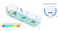
Figure 4. Removal of walls and new baffles reduced swirl and improved mixing. This image shows existing baffling.
Figure 4. Removal of walls and new baffles reduced swirl and improved mixing. This image shows improved baffling.
Rectangular, horizontal or asymmetric vessels. Rectangular vessels are partially self-baffling. Additional baffling occasionally is recommended. Horizontal and asymmetric vessels pose unique challenges. For example, a recent horizontal reactor optimization improved mixing with minor changes to the agitator itself but with a new baffle configuration, as shown in the 3D-CFD model depicted in Figure 4. (This model comes from a study that utilized 3D CFD not only to model flow patterns but also to predict baffles forces for use by the vessel designer [3].)
Side-entry mixers. Don’t use baffles with side-entry mixers. Many applications can benefit from offsets or angle-mounting configurations.
Dip pipes, thermowells, probes and other vessel internals. It’s tempting to use baffles as the structural support for vessel internals. However, careful consideration of the flow patterns around the baffles is necessary because the flow patterns in the vicinity of the baffles are atypical of the bulk motion. Flow velocities on the trailing sides of baffles often are the lowest velocities in the vessel. Recommendations from agitator vendors, often supported by 3D CFD, can be helpful in locating these internals.
Mechanical Concerns
Baffles allow for a stable flow pattern in the vessel, which leads to lower variability mechanical loads on the agitator itself as well as the vessel nozzle and mixing mounting structure.
Forces developed by the agitation system determine baffle thickness and mounting hardware. The agitator vendor should provide the force data necessary to specify baffle thickness. Many years ago, Dr. James Oldshue presented the relationship for baffle design load, Ld, as follows:
Ld = (10,500 Pm × DF)/(B × Tf × N)
where Ld is baffle force in lb, Pm is motor horsepower, DF is the dynamic load factor (normally 2.0), B is the number of baffles, Tf is the tank diameter in ft, and N is in rpm [4].
This formula assumes the baffle force is a constant force perpendicular to the baffle acting in the direction of impeller rotation and is the same on each baffle. The forces are greater on the leading (higher velocity) side of the baffle than on the trailing side.
Generally, in low pressure or open vessels, make baffles the same thickness as the vessel shell, but never less than ¼ in. Always place wall supports on the trailing side of the baffle and uniformly space them along the baffle height.
Baffle force varies with baffle height and time. The force is concentrated at impeller(s) elevation(s). 3D-CFD plots enable visualizing timed-average pressure distributions on both sides of the baffles. Using 3D-CFD analysis for baffle design is most useful when baffle costs are substantial.
Recent studies presented at AIChE [5] used 3D CFD to characterize baffle loads based upon impeller design. The predicted loads then were experimentally validated in the laboratory. This work showed the classic baffle load correlation to be conservative, particularly for axial flow impellers. Specifically, based upon actual power draw, for the radial flow impeller, CFD predicted a maximum baffle force of 9.3 N (versus 15.2 N calculated); for the pitched blade turbine, CFD predicted 4.6 N (versus 14.4 N calculated). Both conditions were at equal agitator power.
A key take-away is that axial flow impellers impart less force on the baffles than radial flow impellers do.
Pressure profiles along baffles can be predicted with 3D CFD. This information is useful in locating baffles supports, troubleshooting or when the costs of high alloy baffles and mounting structures are significant.
In addition to promoting an effective mixing flow pattern, the proper installation of baffles reduces forces on the agitator. An agitator is designed assuming that baffle recommendations have been followed. This is critical because at equal power input, the removal of baffles in a vertical cylindrical vessel will increase fluid force 1.5–2.0 × the initial force on the agitator. Even if the agitator is moved off-center to improve the mixing flow pattern, fluid forces rise similarly [1].
When circumstances require, operating without baffles can result in a stable, but not necessarily optimal, flow pattern as long as vortexing down to the impellers doesn’t occur. Due to the losses in mixing efficiency and increased forces on the agitator itself, operation without baffles requires forethought and rarely is an appropriate retrofit.
Final Thoughts
Baffle recommendations are a critical part of the agitation system design. Because baffles aren’t part of the agitator vendor’s scope, coordination is important — yet frequently overlooked.
When there is uncertainty about the need for baffles or the potential for process change, include baffle clips in the vessel design. This enables the addition of baffles later.
GAIL POGAL is an applications engineer at SPX Flow — Lightnin, Rochester, N.Y. RICHARD O. KEHN is director of engineering and R & D for SPX Flow, Rochester, N.Y. Email them at [email protected] and [email protected].
REFERENCES
1. Kehn, Richard O., “The Effect of Baffles and Mixer Mounting Position on Impeller Fluid Forces,” presented at Mixing XXIII, Mayan Riviera, Mexico, North American Mixing Forum of AIChE, New York City (2012).
2. Paul, Edward L., Atiemo-Obeng, Victor A. and Kresta, Suzanne M., “Handbook of Industrial Mixing Science and Practice,” Wiley, Hoboken, N.J. (2004).
3. Iniguez, Antonio, Kehn, Richard, Kontur, Joseph and Seal, Graham, “Optimizing Agitation for Gold Plants Using Experimental and Computational Techniques,” presented at ALTA Conference, Perth, Australia (2015).
4. Oldshue, James Y., “Fluid Mixing Technology,” McGraw-Hill, New York City (1983).
5. Kehn, Richard O. and Hensel, Edward, “Predicting Baffle Forces Using Both CFD and Experimental Techniques for Both Radial and Axial Flow Impellers,” presented at AIChE Annual Meeting, Salt Lake City, Utah, AIChE, New York City (2015).


