THIS MONTH'S PUZZLER
We recently commissioned a new polypropylene plant. We had modified our earlier design to include internal cyclones in the fluidized beds to keep dust from going to the recycle compressor and cooler. However, the fluid bed reactors don't perform as expected. We're seeing: 1) fines carried over from the first to the second reactor; 2) fouling of the second recycle compressor and cooler; 3) poor distribution in the tubes at the bottom of the second fluid-bed reactor; 4) spikes of excessive heat from the second reactor; 5) plugging in the air locks carrying the product to the purge tank; and 6) temperature and pressure fluctuation in both beds that make it difficult to maintain a steady bed height. Our bed pressure taps and thermowells foul — we've tried heat tracing and purge nitrogen to reduce fouling but without success. What did we do wrong and are there any simple solutions?
START FROM SCRATCH
There are a number of potential causes for the problems witnessed. As always with troubleshooting, we're working exclusively with those problems that have been identified, not the ones missed, accepted as normal, or as yet too small to be recognized. Let's start with Dr. Ishikawa's basic fishbone diagram as a template: personnel, procedures, materials, equipment and other.
Rule out personnel at this point, except for human error in design or construction; it's too early to criticize maintenance.
With the addition of the internal cyclone, startup procedures must have changed. Inserting a cyclone reduces headspace needed for disengaging the solids, increasing pressure drop across the bed because of higher superficial velocity and making it trickier to maintain a steady bed height. Review any other changes in the design and make sure the procedures compensate for them. Look at the shutdown and steady-state operating instructions, too.
Now, consider design errors. Are there instruments to measure the pressure drops across the internal cyclone? If not, add them. Also, look for other instruments the design change should have required. Calculate the superficial velocity in each bed and compare it to the velocity without the cyclone and that used for design of the cyclone — hopefully, this wasn't overlooked during design. If the instruments for making this measurement aren't in place or have become unreliable as a result of the process, add redundant instruments or make changes in the reaction instrument package. Consider external measurements for applications where erosion or fouling are problems, and where internal measurements can't be trusted: gamma-ray scanning or even x-ray may be useful — but remember to remove instruments or they will be fried. Another idea is to develop a computation fluid dynamics (CFD) model of the process. This could be very expensive but would go a long way toward identifying the flow problems you must fix.
What about material of construction and feedstocks? The material of construction is less important because, while the ceramic catalyst potentially might damage the steel, there isn't much chance the prepolymer will. However, just because the feedstock hasn't changed doesn't mean it's right: check the catalyst and prepolymer to ensure they meet ingredient specifications.
Equipment that has changed is likely the main culprit in the process. Start with the internal cyclone. Cyclones are efficient in collecting particles around a certain diameter. According to "Perry's Chemical Engineers' Handbook," 8th ed., p. 17-36, efficiency (Eo) is inversely proportional to Dpth (the 50%-cut particle size — below that size collection drops off — not to be confused with minimum cut size): Eo ∝ [(ρp – ρg)/ μg]1/2, where p represents the particle, g represents gas at inlet conditions, and μ g is the average gas viscosity. Efficiency is proportional to the square root of the density differential over the gas viscosity. Because gas density changes little, it's nearly irrelevant. Therefore, Eo,actual/Eo, design∝ ( μ g, design/ μ g, actual)1/2. A change in gas viscosity, caused by a shift in temperature (in most cases) or pressure, alters efficiency. Gas viscosity is impossible to measure directly but perhaps could be inferred by change in density.
However, an assumption here — uniform diameter — could knock everything into a cocked hat. If particles clump together or are of an irregular size (aspect ratio > 1), even momentarily, the cyclone cut size could increase, swamping the cyclone with large particles dumping onto the fluidized bed. This could cause flow problems starting with the product discharge to the second bed. Poor velocity distribution leads to poor heat transfer.
Flow problems could create hot spots in the reactor. Catalysts would become hot from the exothermic reaction, causing localized clumping of polymer. The first place to look for fouling is in the distribution plate or tubes at the bottom of the reactors.
As for temporary solutions, consider adding cleanout plates to the air locks and lowering the bed level in the first reactor. The plates can be cut into the sides of the air locks to allow access to the rotors. I've seen air locks frozen from buildup or unable to flow beads. Lowering the bed level likely will reduce the throughput of the entire plant, so confirm instrument ranges and operating instructions for a safe turndown rate. Eventually, you'll want to determine if changing a nozzle location, in particular the discharge of the cyclone, will reduce carryover. Sometimes, it's as simple as installing a diverting plate to prevent interaction. A CFD model could be instrumental in sorting this out.
Ideally, the process equipment should be disassembled for internal inspection of the bed — pay particular attention to the distribution plate and tubes at the bottom of the reactor and the inlet of the cyclone. Next, look at the air locks on the first bed and at the recycle compressor discharge and inlet of the second bed. You'll also want to inspect the product line connecting to the receiver feeding the second fluid-bed reactor. Look for solids buildup; take samples for scanning with an electron microscope.
Dirk Willard, senior process engineer
Ambitech Engineering, Joliet, Ill.
JUNE'S PUZZLER
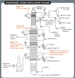
The atmospheric tower (Figure 1) of our crude distillation unit performs adequately but we'd like to improve its efficiency and capacity as well as eliminate a few nagging problems. We've run a few experiments to justify simulation runs. Gamma scans have shown flooding in the sieve trays at and above stage 8 in the heavy gas oil (HGO) section of the column when we tried to increase crude feed. We also see some channeling in the structured packing in the light gas oil. In addition, we're concerned about whether the type-304 stainless steel used for the structured packing in the naphtha pump-around and elsewhere is adequate now that we've increased the ratio of heavy to sweet crude; samples in that section show higher H2S concentration than ever before. We have caustic injection quills downstream of the desalters to neutralize HCl but we're worried about downstream sodium. Other problems include a slightly higher pressure between the outlet of the air condenser and the vent discharge to the sour gas knockout drum. Occasionally, we're seeing dry trays between stages 13 and 20. Also, the control valve for the HGO steam stripper sometimes runs 100% open, restricting tower throughput. What should we include in future analyses and what do you recommend to improve tower performance?
Figure 1. Flooding and channeling, as well as a higher H2S level, afflict the tower.
Send us your comments, suggestions or solutions for this question by May 16, 2014. We'll include as many of them as possible in the June 2014 issue and all on ChemicalProcessing.com. Send visuals — a sketch is fine. E-mail us at [email protected] or mail to Process Puzzler, Chemical Processing, 1501 E. Woodfield Rd., Suite 400N, Schaumburg, IL 60173. Fax: (630) 467-1120. Please include your name, title, location and company affiliation in the response.And, of course, if you have a process problem you'd like to pose to our readers, send it along and we'll be pleased to consider it for publication.


