Make the Most of Variable Frequency Drives
A variable frequency drive (VFD), sometimes also called an adjustable speed drive (ASD), is an electronic device that allows users to change the speed at which a motors runs. The combination of a VFD with a motor is becoming increasingly popular as a final control element because it consumes less power than a motor running at full speed and a control valve. Indeed, the U.S. Department of Energy (DOE) is encouraging the use of VFD for motor control to reduce power consumption [1]. However, obtaining good control depends upon proper selection and installation of the drive as well as understanding how control may differ with a VFD.
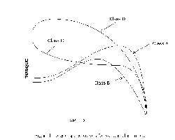
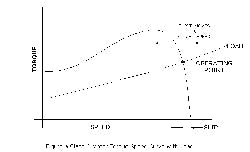
The VFD is one part of a total system that includes a motor and a load. The motor acts as a power transducer, converting electrical power to rotational mechanical power. AC induction motors, 600V and below, often are paired with a VFD. (We’ll discuss DC motors later.) These AC motors fall into classes with different torque speed curves (Figure 1). Most drive manufacturers assume use of a Class A motor and that the torque speed curve will be almost linear at the operating point (Figure 2). The VFD will shift the whole curve left or right to change the operating point. Note the “slip” in the figure. Every motor suffers from some slip or difference between rotor and stator fields. This is quite different than stiction, the term used with control valves for the needed stem force to overcome static friction. The load — mechanical conveyor, pump, fan, compressor or the like — has inertia, rotational friction and stiction. The process also has dynamic characteristics that may change when using a VFD instead of a control valve. It takes time to accelerate the load to operating speed and this is proportional to the inertia and the motor torque.
Figure 1 -- AC motor classes: Each class features
a distinct torque speed curve.
Click on illustration for larger image.
VFD Basics
Today VFDs use a technique called pulse width modulation (PWM). First AC power is rectified to DC and filtered. Next, a solid-state semiconductor called an insulated gate bipolar transistor (IGBT) creates a voltage waveform to the motor that is a series of pulses of varying widths. The result is a varying frequency AC sine wave. The switching frequency determines the shaft rotational speed. Because the power waveform from a VFD isn’t purely sinusoidal, it’s important to only use motors specially designed to run with PWM VFDs — these are “inverter duty” motors, Class F winding. If a conventional motor is used, it may burn out.
A VFD also has other control electronics; these may include current, voltage and speed sensors.
The VFD electronics has limitations that affect control performance. One limitation is current. The inrush peak starting current of an “across the line” starter, one without a VFD, is eight times the full load current. Such a current would damage a VFD’s rectifiers and semiconductors. Another constraint: the drive electronics is designed to prevent the motor flux from saturating the core.
The process transmitter sending its output signal to the proportional-integral-derivative (PID) controller that acts as the outer loop senses the process dynamics; its output is cascaded to the VFD.
Within the drive electronics are algorithms that control the electrical motor power, frequency, voltage and current. The current and speed set the motor torque. So the drive doesn’t control just the speed, it also regulates the torque delivered to the rotor shaft. This torque produces the rotational force applied to the load (pump, etc.) that powers the process.
Figure 2 -- Class A motor: The curve with load is
almost linear at the operating point.
Click on illustration for larger image.
Properly understanding the dynamics of a VFD control loop requires considering all elements of the system and how they interact.
Drive Control Strategies
A computer program connected to the drive or a human machine interface (HMI) front panel enables inputting data about the load and the motor as well as setting the drive control strategy, which usually takes advantage of proprietary functionality. This strategy together with the load dynamic behavior determines performance. Loops within the drive electronics can be configured to control speed (through an external encoder), voltage, current and, in some cases, motor flux. These are the inner loops of the process control cascade. When tuning, remember that the inner loops must be at least five times more responsive than the outer loop. Another term to describe performance is bandwidth; it’s inversely proportional to the time constant of the controller/motor with no load.
VFD manufacturers offer models with varying performance and cost. So, assess which is the best drive for the particular application.
Most drives have a defined, configured startup sequence that is to be run with the load disconnected. During this sequence the drive powers the stator and makes measurements that determine the characteristics of the motor. These motor constants then are used to tune the internal electronic program.
Drive control strategies generally fall into three categories [2]:
Volts per Hertz control. This is the simplest method. As seen in the torque speed curve (Figure 2), the region to the right of the peak can be considered linear — therefore controlling the frequency will regulate the shaft speed. The supplied voltage is v = ir + dλ/dt, where λ is the flux linkage. The derivative term is directly related to the rotation; so the rotational speed is proportional to voltage, thereby volts per hertz. At high speeds the ir term is negligible. The speed error is large at less than 10% of the rated rpm. Some configurations can compensate for this. This strategy is recommended for fan and pump applications. The resolution is about 0.5% base speed over a 40:1 range.
Another problem with this strategy is the reduced motor torque at low speeds. This can be a serious problem conveying sticky solids or slurries. The torque decreases because the motor and wire ir drop is a larger percentage of the supplied power. Using a larger wire size can help solve this problem.
Constant-slip current control. This strategy regulates the slip or difference between the electrical speed and the actual speed. This is configured two ways, either optimum torque (maximum torque per amp) or maximum efficiency. Based on the motor constants found during configuration or testing, the drive electronics will calculate the flux linkages to avoid saturation. Two inner loops are used for this strategy. The speed command, usually the output from the outer process controller, is cascaded to a proportional-integral (PI) controller in the drive electronics. This PI controller compares the shaft speed to the set point and provides an output signal to a torque controller. This controller converts the torque set point to a current required to achieve that torque. A current sensor then corrects this current.
This strategy relies on three cascaded controllers. To obtain stable behavior each inner control loop must be several times faster than the loop it’s fed from. Anti-reset windup should be used for each loop. To accommodate the sluggish torque response, the drive performs more slowly than with the volts per hertz strategy. The stator current is controlled at or just slightly above its rated peak value during start up. This strategy has 0.1% of base speed regulation across an 80:1 range.
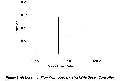
Figure 3 -- Blending issue: Original VFD led
to inaccuracies in component addition.
Click on illustration for larger image.
Field-oriented control. The basis of this strategy is that the maximum torque between the rotor and stator magnetic fields occurs when the rotor current vector is perpendicular to the stator field (per Lorenz’s force equation). The current control is calculated from the torque command and an estimate of flux. The strategy can be implemented two ways: direct and rotor-oriented where Hall effect transducers measure the flux, and indirect where the flux is estimated. Industrial applications don’t employ flux sensors. This method offers improved transient performance. A 50-hp motor with load reaches full speed in 2 sec. and peak current remains at a steady-state value. High performance drives using this strategy have 0.001% base speed regulation across a 120:1 speed range. Because this method uses estimated machine constants, performance will deteriorate if the constants are incorrectly entered. The problem is most severe at low speeds. If the online machine parameter estimates aren’t correct, the drive will experience “hunting.”
Regardless of control strategy, as already noted, the drive changes the voltage or current to the motor via modulation. The IGBT is a switch either on or off. PWM produces a change in value by alternating the switching sequence. In this manner the output stator current will resemble a sine wave with steps inserted. The switching frequency, usually a configured entry, will determine how well the waveform will track. It’s preferable that phases are sequenced, not all switched at once. This reduces the effective switching speed and results in an offset between the actual and desired current, therefore necessitating some closed-loop strategy.
The resulting waveform produces a quantized output. The root-mean-square value actually will vary in discrete intervals. From a closed-loop perspective this injects a non-linear term in the analysis that will create limit cycles, especially at high process gains.
DC Motors
These motors are classified according to how they are wound. Motor performance, usually shown as a torque speed curve, differs with winding design.
In the case of a shunt wound or separately excited motor, a constant DC voltage is applied to the stator winding while a variable voltage is applied to the rotor winding. A permanent magnet DC motor behaves similarly to a separately excited one. A shunt wound DC motor has a single voltage source that powers both the rotor and stator. The shunt wound, permanent magnet and separately excited motors have a linear torque speed curve and, thus, can provide better speed regulation with varying loads. They come in several winding variations, such as compound windings.
In a series motor, the stator is wired in series with the rotor. The torque speed curve for this motor has a parabolic relationship. This motor frequently is used for high mechanical inertia loads, elevators, cranes, etc.
Proceed With Caution
There’s a misconception that a VFD provides better resolution than a control valve. This isn’t always the case. Virtually every modern electronic control system today features some sort of digital or microprocessor control. There has to be an interface between the analog domain and the digital one. Both AC and DC drives use digital-to-analog (D/A) converters. These converters don’t provide infinite resolution — rather they quantize the signal. This produces a so-called quantization error. The number of digital bits is inversely proportional to the error. Process applications frequently use a “10 bit” D/A converter. This breaks up the output signal into 210 or 1,024 discrete levels from the zero point to the maximum.
For example, consider a DC motor speed control powering a gear pump. In a simulated flow control problem, with 10-bit output resolution for a 22-gpm maximum pumping system, this error amounts to 0.03 gpm for a separately excited motor and 0.2 gpm for a series wound motor.
In another case, a continuous process employed a positive displacement pump powered by a VFD-controlled AC motor. Several fluids were blended and the final product quality depended on an exact ratio of all fluids. The precision of this process can be compared to that of in-line pH control — a very small deviation in reagent ratio may result in very large pH changes. This process suffered quality problems. Mass-meter flow rate data at the same set point were archived in an historian and gave the histogram in Figure 3. The positive displacement pump curve has a slope of 0.1 gal/rpm flow. The motor synchronous speed is 1,800 rpm. The adjustable frequency AC drive specification has 514 frequency divisions for the published resolution. The flow controller was trying to find the right output, midway between these peaks, but couldn’t. This caused the process signal to hunt around the set point. Always suspect a quantization problem if a bi-nodal process variable histogram distribution occurs with a continuous steady-state output signal. The plant replaced the VFD with one that had better output resolution and solved the problem. This example is extreme; however it demonstrates that the problem can occur. Drives available today have much better resolution, 0.01%.
As the above illustrates, a VFD can affect the plant. Startup and shutdown operations differ from those with a full-speed pump and control valve. Remember with a VFD you’re controlling the power applied to the load while with a control valve you’re introducing a controlled restriction to the power already applied to the load.
Variable speed pumps offer a linear response within a given inlet and discharge pressure range. However, you must limit the minimum speed to ensure that the pump’s discharge pressure never drops below the static pressure downstream — otherwise, a disastrous flow reversal can occur. Also, you must add an on-off valve and coordinate it with the variable speed pump to provide positive flow shutoff.
Loop Considerations
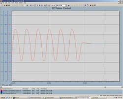
Just as we have acceleration and deceleration lanes on and off highways, drives have acceleration and deceleration ramps. These ramps are used to limit the motor starting current. They act as integrators in the loop dynamics. The default setting usually is 5 sec. to 10 sec., a typical flow loop reset value. If the integrator in the PI or PID controller is set faster than the VFD ramp, the resulting closed-loop performance will exhibit a limit cycle. This cycle isn’t due to reset windup or saturation but, rather, occurs because the controller integrator is acting faster than the load can respond. Many controllers offer a feature that allows the reset action to be changed based on actual valve travel. Configure an auxiliary VFD output signal proportional to the actual load to the controller function block to eliminate the limit cycle.
Another factor is the process time constant. For drive-powered liquid flow control loops, the process time constant is larger during start up; in contrast, flow control loops with control valves have a smaller time constant. The loop will perform sluggishly during start up compared to a flow loop with a control valve and pump powered by an induction motor without a drive.
Always check the drive’s deadband setting, which is used to reduce the reaction to noise. If not carefully adjusted, it can add deadtime and cycling.
An Attractive Option
A VFD can provide much needed power reduction and good operation. Torque and amps developed by an AC motor will determine the size of VFD needed for an application. Always size a VFD based on the load, which is expressed in amps, never on horsepower alone.
As with any instrument or control device, making the most of a VFD requires care and knowledge, including an appreciation of how control with a VFD differs from that with a control valve.
Figure 4 -- Problem avoided: Reset inhibiting of
controller eliminated limit cycle.
Click on illustration for larger image.
Web-Exclusive Tips for Success
Making the most of a VFD requires paying careful attention to installation as well as staff skills and training.
Installation considerations. You can’t just mount and wire a VFD any which way. You must follow national electrical codes (NEC) as well as the manufacturer’s recommendations. Pay particular attention to the following six aspects:
1. Wire and cable size, insulation and shielding. Shielded power cable is necessary to prevent interference with other plant instrumentation and controls. Lengths are important; remember at reduced motor voltage and rated current, a larger percentage of the power delivered is dissipated in the power cable.
2. Power distribution. A grounded secondary is preferred. Use the AC line impedance to determine if an isolation transformer or line reactor should be installed.
3. Grounding. Building steel can be used. Ground the shields at a single point to avoid ground loops.
4. Drive installation. For best noise immunity separate the power and signal wiring. Mount the drive in a place that’s accessible; see the NEC for required distances. Consider heat dissipation — the VFD electronics generates heat that must be removed. Remember, the cooler the electronics, the longer the life.
5. Reflective wave issues. PWM waveforms create fast rise-time waveforms on the power cables. The peak value of these waves can be high and cause premature insulation breakdown. Power cable with XLPE insulation is recommended.
6. Electromagnetic interferences. Because of the high frequency components in the PWM waveform, the VFD generates interference. Twisted, shielded cable is recommended for the drive wiring.
A motor and load controlled by a VFD may suffer premature bearing failure and lubricant chemical breakdown due to electrical discharge of high voltages induced in the shaft, so-called electric discharge machining or EDM [3]. The problem is relatively new and is attributed to common mode voltage being induced in the shaft due to common mode voltage between each phase and the neutral. The fast transients generated by the IGBT devices cause high frequencies that are induced in the shaft. The problem can be alleviated by several methods, one of which is to use shaft-grounding bushings.
Always Verify:
1. Input supply voltage is landed on the correct terminals.
2. Output wiring going to the motor is landed on the correct terminals.
3. Control wiring is landed on the correct terminals.
Staff skills. Plant personnel don’t need to be rocket scientists to program VFDs — reasonable reading skills coupled with some application knowledge and motor information will suffice.
The first task is to gather as much information about the application as possible. How will it be started and stopped? Will a two-wire or three-wire control start the drive? Will it undergo a controlled ramp to stop, will load determine how long it will stop by using a coast to stop, or will the drive stop very fast and dissipate the energy through a dynamic brake? How will the drive be controlled? Will it need an analog signal or a digital signal commanding a preset speed? Will a 4-to-20-mA signal or a 0-to-10-V signal control the drive? Will the drive need to be configured to give an analog output to feed another process or another drive? Will the application require the use of a programmable digital output? Is it necessary to program the drive to close a set of “dry contacts” once it’s achieved a certain speed, using that as an input to feed a start command to another drive or another process?
Next, access the motor and accurately record all of the data from its nameplate:
1. the rated volts — most industrial AC motors are either 230 or 460 V;
2. the full load amps (FLA), the maximum current the motor is expected to draw under fully loaded conditions — this is probably the most important piece of information;
3. the frequency, which normally is 60 Hz but can vary depending on where the unit will be installed; and
4. the rated rpm — this is the load speed at which full load torque is delivered. A very useful formula to keep at hand is hp = (torque) × (speed)/ 5,250, with torque in lb-ft and speed in rpm. Slip affects this, so, an AC motor rated for 1,800 rpm may really only run at 1,750 rpm.
Finally, you’re set to program the drive. Assuming that it’s been installed properly by qualified individuals, the drive will have the appropriate AC power and control voltages. Status lights on the front of most drives will indicate if the drive is in a ready or faulted state. They also will tell you the status of the communications of the drive.
Some AC drives will have assisted startup routines. These types of programs actually will prompt you for the information needed for most applications and commonly adjusted parameters.
VFD training. All AC drive manufacturers offer drive programming training courses or “lunch and learns.” These, when presented properly, can provide a great foundation to build upon.
Understanding the basics of how a VFD works is crucial. This should start with the fundamentals of magnetism, include details about how AC and DC motors operate, the role of speed and torque, and then how the VFD controls the stator and rotor of an AC motor by rectification and using transistors to invert DC voltage back to a voltage an AC motor can use to rotate.
Robert Heider is an adjunct professor in the Department of Energy, Environmental and Chemical Engineering at Washington University, St. Louis. Clay Lynch is VFD and MCC product manager at French Gerleman Electric Co., Maryland Heights, Mo. E-mail them at [email protected] and [email protected].
References
