Achieve effective heat exchanger control
|
Related articles Heat Transfer Research forms heat exchanger design task force Prevent heat-exchanger plugging Reviewing the use of fouling factors in heat exchanger design |
Most plants heavily rely on shell-and-tube heat exchangers with liquid flowing through the tubes and steam on the shell. To control the liquid outlet temperature (the controlled variable in control engineers’ terminology) for such a steam heated exchanger, several process equipment configurations are possible, including:
- control valve on the steam supply
- control valve on the condensate
- liquid bypass with one or two control valves.
In this article, we’ll focus on the first configuration. Future articles in the series will look at the others.
The process operating line
In selecting the configuration, designers always consider the process issues, such as the requirement for condensate return, but customarily defer the control issues to those who develop the Process and Instrumentation Diagram (P&ID). This practice needs to change because most modern designs are model-based and the relationships in the model allow generating a graph known as the process operating line that’s the basis for evaluating the control issues.
The process operating line is a plot of the steady state or equilibrium values of the controlled variable (liquid outlet temperature) as a function of the controller output. In a sense the process operating line is one approach to implement the “you have to understand the process” philosophy that’s the essence of process control. Important aspects of this graph are:
- Limits of process operation. The minimum and maximum limits on the control valve position are usually 0% and 100% — however, process problems potentially may arise with operation in certain parts of this range.
- Departure from linearity. Departures less then 20% won’t noticeably affect loop performance. However, departures of 50% or greater will be noticeable and are one source of tuning difficulties.
- Regions where the operating line is flat. The changes in the controller output have no effect on the process in such a region, making it a dead zone. The controller may perform well on both sides of the dead zone but won’t make a smooth transition from one side to the other.
- Regions where the operating line is vertical. The process sensitivity within such a region will be very large, causing the loop to be unstable. This will lead to cycling from one side of this region to the other.
- Effect of process operating variables. Throughput is one such variable, especially in utility processes and batch processes.
Note that the items relate to process engineering issues — not linear systems theory (LaPlace transforms and the like) normally taught in academic courses.
Operating limits
Normal operating conditions clearly should fall between the minimum and maximum limits. If not, either the process design is deficient or the process isn’t running under the conditions for which it was designed. The culprit most likely is the latter; some plants “evolve” from design conditions.
The other mistake is to assume that the process is always operated under its normal operating conditions. We experience a variety of disruptions to production (changes in raw materials, upsets in utility systems, equipment problems, etc.). This is when we are likely to attempt to operate the process beyond the limits. The consequences include cycling conditions (induced by the process, not the controller tuning), windup that isn’t addressed by the windup prevention mechanisms as normally configured, etc. The controls need to recognize the presence of the limits and take appropriate actions instead of attempting to operate beyond the limits.
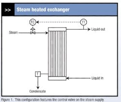
Consider the exchanger with its control valve on the steam supply. The condensate is discharged through a steam trap into the condensate return system. The liquid is a hydrocarbon fluid that enters at 150°F. The steam supply pressure is 75 psig. Under normal operating conditions, the liquid flow rate is 1,000 lb/min; however, occasionally liquid flow rates up to 4,000 lb/min are experienced. Consequently, the control valve must be oversized for the requirements of normal operating conditions. Of course, further oversizing is the norm. For this example, the control valve is oversized by about a factor of four (relative to what’s required for normal operating conditions).
A common misconception is that every control issue pertains to some aspect of process dynamics. In practice, many if not most of the problems with the controls have their root in the steady state behavior of the process.
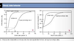
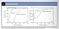
The steady state behavior of the exchanger can be understood from the graphs in. Presents the shell pressure as a function of the steam valve position. Figure 2b shows the liquid outlet temperature as a function of the steam valve position — this is the process operating line for the exchanger. The term “process” is somewhat of a misnomer because the valve characteristics (valve size, inherent valve characteristics, etc.) also are incorporated into the operating line. This is why there are two lines, one for a linear valve and one for an equal-percentage valve.
Maximum heat transfer rate
Two constraints can impose the upper limit for exchangers and other heat transfer processes:
Media limited. The process is capable of condensing more steam than can flow through the control valve. In this case, the control valve would be effective up to 100% open.
Heat transfer limited. The maximum steam flow is determined by heat transfer, that is, by UAΔT. Because control valves are commonly oversized, this is the most common situation.
The maximum possible control valve opening is always 100%. This gives the maximum shell pressure, the maximum heat transfer rate and the maximum liquid outlet temperature. Increasing the steam valve opening always increases these three variables. But for large valve openings, the increase will be very small — so small, in fact, that it’s practically zero. Once the shell pressure approaches the steam supply pressure (75 psig), the exchanger approaches the heat transfer limit and is said to be “maxed out.”
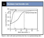
For heat transfer processes, the control valve normally is effective up to about 90% of the maximum heat transfer rate. For a constant liquid flow and liquid inlet temperature, the heat transfer rate is proportional to the liquid temperature rise from inlet to outlet. If the shell pressure is equal to the steam supply pressure, the shell steam temperature is 288°F. The maximum possible increase in liquid temperature is from 150°F to 288°F or 138°F. The control valve should be effective for temperature increases of 90% of 138°F or 124°F. This corresponds to a liquid outlet temperature of 274°F.
Figure 3 indicates the valve openings for a liquid outlet temperature of 274°F. For an equal-percentage valve, this is a valve opening of 50% (actually 51%, but let’s round valve openings to the nearest 5%). For a linear valve, this is a valve opening of 15%! This is typical for oversized valves with linear characteristics. If you install a linear valve, it must be properly sized for the process operating conditions.
One of the issues previously raised pertained to flat regions of the process operating line. The slope of the process operating line is the process gain or process sensitivity (again, “process” includes the control valve). A decrease in the process sensitivity has the same effect on loop performance as a decrease in the controller gain, that is, the loop responds more slowly. For an equal-percentage valve, the controller can be effectively tuned and will give consistent performance for valve positions up to 50%. But above 50% the process gain is very small and approaches zero as the valve opening is increased. Even process operators will observe this, saying “Once the valve is half open, it has no effect on anything.”
If the controller gain is increased to compensate for the reduced process gain, the higher gain will give problems at lower liquid outlet temperatures. This is one case where some people will propose characterization functions, scheduled tuning or other approaches commonly referred to as adaptive control (but, in reality, these are nonlinear controls). A simple approach (scheduled tuning) would be to use one value of the controller gain for valve openings (controller outputs) less than 50% and a higher value for controller outputs above 50%. Unfortunately, the actual cutoff point depends upon operating conditions, especially throughput.
Minimum heat transfer rate
Let’s assume that the condensate from the steam trap flows into a drain. Figure 2a indicates that the shell pressure is below atmospheric when the steam valve position is less than 29% for the equal-percentage valve or 6% for the linear valve. Under these conditions, the condensate won’t flow out of the shell. If the condensate flows into a condensate return system, the minimum shell pressure is approximately atmospheric pressure.
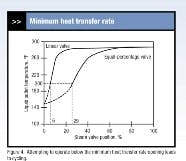
This imposes a minimum heat transfer rate on the exchanger. Atmospheric pressure in the shell corresponds to a shell temperature of 212°F. Because the liquid enters at 150°F, heat will be transferred to the liquid. This heat transfer rate is the minimum that can be continuously sustained by the exchanger in Figure 1. The minimum heat transfer rate gives a liquid outlet temperature of approximately 200°F, regardless of the valve characteristics.
Figure 4 illustrates the effect on the process operating lines. The minimum heat transfer rate corresponds to an opening of 29% for the equal-percentage valve and 6% for the linear valve.
Attempting to operate below this minimum leads to a cycling condition. The following scenario occurs for the equal-percentage valve:
- The controller positions the valve to less than 29%.
- The shell pressure drops to atmospheric and the shell begins to fill with condensate. This reduces the effective heat transfer area and the heat transfer rate.
- The liquid outlet temperature drops below target, causing the controller to increase its output to the control valve and admit more steam to the shell.
- When the shell pressure exceeds atmospheric pressure, the condensate is forced from the shell, exposing the entire heat transfer area.
- The heat transfer rate increases, which drives the liquid outlet temperature above its target.
- The controller decreases its output to the control valve, eventually giving a valve position less than 29%. This causes the cycle to repeat.
How do we avoid operating the process below the minimum heat transfer rate? For normal operating conditions, we could impose a minimum of 200°F for the liquid-outlet-temperature set point. Unfortunately, a variety of variables, including throughput, affect the value for this limit.
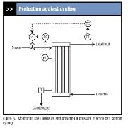
Perhaps the surest way to avoid such conditions is to monitor the shell pressure and provide a shell pressure override (Figure 5). For digital implementations, the only additional hardware is the transmitter for the shell pressure. The remainder is implemented in software. For exchangers that discharge the condensate to a drain, the set point for the shell pressure controller would be slightly above atmospheric. For exchangers that discharge into a condensate return system, the set point for the shell pressure controller must be slightly above the pressure required to force the condensate back to the boiler house.
Implications
Figure 6 presents the process operating lines with the limits on operation indicated. Let’s examine each of the aspects previously mentioned:
Limits of process operation. When expressed in terms of the liquid outlet temperature the operating limits are 200°F and 274°F, regardless of the inherent valve characteristics. But when expressed in terms of the control valve position the operating limits definitely depend upon the type of valve:
- For an equal-percentage valve, the minimum and maximum limits correspond to valve positions of about 30% and 50% (again rounding to the nearest 5%), respectively. So, we’re using the valve only over 20% of its full range. This is the customary consequence of oversizing an equal-percentage valve. Fortunately, we’re often able to get by with this.
- For a linear valve, the minimum and maximum limits correspond to valve positions of about 5% and 15%, respectively. These are small valve openings coupled with a narrow operating range. As is normally the case for an oversized valve, a linear valve isn’t a good choice.
Departure from linearity. Over the region of 30% to 50% for the equal-percentage valve, the departure from linearity is modest and shouldn’t necessitate any form of scheduled tuning or the like.
Regions where the operating line is flat. For the equal-percentage valve, such a region exists for valve openings above 50%. Even if the controller gain is increased dramatically, the liquid outlet temperature won’t be controlled very effectively in this region.
Regions where the operating line is vertical. The operating lines in Figure 6 don’t exhibit this characteristic.
Effect of process operating variables. Throughput has the most significant influence on the operating lines. (We’ll examine this in the next section.) Other variables such as steam supply pressure and liquid inlet temperature for the exchanger also influence the operating lines. Usually the effect of such variables is less than the effect of throughput — but this is a generalization for which exceptions definitely exist. So, for any process in which you expect a significant change in some operating variable, evaluate its impact on the process operating lines.
Effect of throughput
Figure 7 presents the process operating lines (equal-percentage valve only) for liquid flows of 1,000, 2,000 and 4,000 lb/min for our exchanger. The heat transfer generally increases as the flow increases but not in a linear fashion. The shape of the operating lines is basically the same for all, the major difference being that the increase in temperature from liquid inlet to liquid outlet decreases as the liquid flow increases.
Figure 7 also illustrates the effect of throughput on the valve positions corresponding to the minimum and maximum heat transfer rates. The effect of increasing throughput is to increase these valve positions; however, the difference between the valve positions for maximum and minimum heat transfer remains at about 20%. Over this range, all of the operating lines exhibit only a modest departure from linearity.
While some processes, e.g., in refining, operate at essentially constant throughput, others, such as most utility processes, are expected to handle significant changes in throughput. For example, most industrial boilers are designed for a turndown ratio of at least 4:1.
Batch processes also can exhibit extreme variations in throughput. Consider a batch reactor with a jacket for removing heat. The contents of the reactor, that is, the reacting media, determine the dynamics of a production-scale reactor. The dynamics associated with the jacket are far shorter, which means that the jacket is essentially at an equilibrium state that reflects the conditions within the reactor. As the conditions within the reactor change, the jacket basically tracks those conditions.
For batch reactors, the turndown ratio pertains to the heat transfer rate between the reactor and the jacket. For many batch applications, this heat transfer rate varies substantially during the batch. Typically the heat transfer rate is highest in the early stages and usually drops off considerably during the later stages. Turndown ratios of 50:1 are experienced in practice — this has major repercussions on all aspects of the process (jacket design, valve sizing, cooling/heating media flow measurement, controller tuning, etc.).
For operating lines such as those in Figure 7, the temperature controller usually must be tuned to give acceptable performance for the throughput for which the slope of the operating line is the steepest. This is where the process will have its highest sensitivity, which in turn requires the smallest value for the controller gain. The steepest slope decreases in magnitude as the throughput increases. Consequently, the higher the throughput, the lower the process sensitivity and the higher the controller gain required to achieve consistent loop performance.
This is another potential application for scheduled tuning. A measurement is required for the liquid flow through the exchanger. For low liquid flows, the process gain is high, so a low controller gain is appropriate. As the liquid flow increases, the controller gain should be raised (approximately proportional to the increase in liquid flow). These applications of scheduled tuning usually are successful. But when other operating variables are added to the mix, the logic becomes more complex and success less assured.
