When qualifying valves for a pressure-reduction application, chemical plant engineers must consider several factors. Initially, they must determine whether or not the application requires a control valve to be effective.
Would a self-contained or piloted regulator be sufficient? To make this decision, plant personnel should consider:
The pressure drop, or the difference between P1 and P2.
The set point.
The potential for large flow variations.
The level of importance of regulation/control.
If it meets the design criteria, a regulator will prove a more effective means of pressure reduction in almost all cases. In addition to lower overall costs, a regulator offers other advantages ," most important of which is fast response.
This responsiveness is of great value when applied to noncompressible media, or in applications in which delayed shutoff might blow a safety relief valve. Additionally, regulators are sensitive to load variations commonly experienced in heating or cooling pressure control.
Considering the droop effect
After choosing a regulator over the control valve option, however, the plant must consider the droop effect. Droop is an inherent characteristic of all self-operated and pilot-operated regulators. It is expressed as the deviation of pressure from the set value that occurs when a regulator travels from the minimum-flow position to the full-flow position.
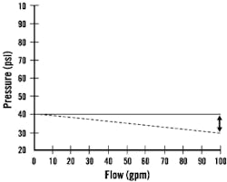
Fig. 1 shows the effect of droop in a regulator set at 40 pounds per square inch (psi) as the valve travels from the minimum-flow position to the full-flow position. The droop is expressed by the difference between the dotted line and solid line. The dotted line represents the actual controlled pressure attained, and the solid line represents the line of perfect regulation.
Figure 1. Droop Effect in a Regulator Set at 40 psi
The dotted line shows the droop effect as a valve travels from the minimum-flow to the maximum-flow position.
Consider the application shown in Fig. 2, which indicates a 100-psi water pressure available in a building. To best operate the equipment and taps, it is necessary to reduce the pressure to 40 psi. A pressure-reducing valve can be installed on the service line to handle this reduction.
When there is no demand for water, no flow is required; therefore, the regulator is in the closed position. As demand for water increases to the full capacity of the valve, the regulator moves to the fully open position. However, because the regulator will droop with increasing flows, the set pressure of 40 psi to the building will not be maintained. Why not?
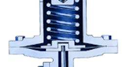
An increase or decrease in the amount of force applied to the spring establishes the set point for a self-contained regulator. In most cases, this is done with an adjusting screw. A clockwise turn of the adjusting screw threads the screw further into the spring housing, compressing the spring and increasing the set point. A counter-clockwise turn of the adjusting screw allows the spring to relax and decreases the set point.
Figure 2. Typical Pressure-Reducing Valve Application
A pressure-reducing valve installed on the service line is intended to decrease the water pressure from 100 psi to 40 psi. However, the droop effect could adversely affect pressure-reduction operations.
Downstream pressure is transmitted to the diaphragm, either directly or via a downstream tap. When downstream pressure beneath the diaphragm exceeds 40 psi, the spring compresses and the valve closes.
When the pressure beneath the diaphragm decreases, the valve opens once again. In other words, the spring will not expand or contract unless a decrease or an increase in the pressure (force) opposing it occurs.
When downstream demand increases, the valve travels toward the fully open position. This allows the spring to expand, "adjusting" the set point ," but this time from the diaphragm instead of the adjusting screw.
Reducing droop
As stated earlier, droop is an inherent characteristic in any self-operated or pilot-operated regulator. However, it can be minimized. The extent of droop is determined by three factors: diaphragm area, spring rate and stroke length.
An increase in the diaphragm area, a decrease in the spring rate and/or a decrease in the length of the valve stroke can reduce the droop. It is important to remember that these factors are interrelated.
Diaphragm area. The diaphragm area is restricted by economic and practical reasons. Larger diaphragms tend to increase the overall cost of the regulator because they require larger spring housings, heavier bolting, etc.
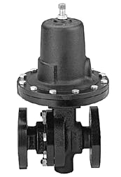
Shown here is a typical regulator valve.
Spring rate. Design engineers typically will use the lowest-rate spring that will allow an adequate range of pressure adjustments (set points) and still retain sensitivity to small changes in pressure. It is possible to reduce the droop with low-rate springs, but plants run the risk of making the regulator too sensitive, which will create instability. Plus, the range of set points with a very light spring might prove too narrow for general industrial use. By lengthening a heavier spring, plants can increase the sensitivity, but this practice often is restricted by economics and valve size.
Stroke length. The distance a spring is allowed to relax in proceeding from minimum to maximum flow can be reduced to decrease the droop. Plant personnel establish the set point for any self-contained regulator by increasing or decreasing the amount of force applied to the spring (spring compression). In most cases, this is accomplished with the adjusting screw. When flow conditions downstream cause the valve to move toward fully open, this also "adjusts" the spring from the bottom. Thus, when the valve opens to compensate for additional flow demand, the spring is allowed to relax and the set point decreases. To minimize the droop, design engineers can use regulators offering a shorter-than-normal overall stroke length.
An adjusting screw can increase or decrease the force applied to the spring, increasing or decreasing the set point for a self-contained regulator.
Pilot-operated valves
Pilot-operated valves experience less droop than self-contained valves. The additional sensitivity is obtained by a combination of the pilot diaphragm, pilot spring and pilot valve stroke. The required stroke in most piloted valves is minimal because little flow is required to load the diaphragm of the main valve. Only minute pressure changes are necessary to fully move the pilot spring. Droop will occur, but it will not be dramatic.
Choosing the best valve
Most self-contained regulators will demonstrate a droop effect of approximately 10 percent to 20 percent of rated capacity. For higher set points, heavier springs are used, and droop could be considerably higher. Most piloted-operated regulators will demonstrate a droop between 2 percent and 5 percent.
Most applications do not require a valve to throttle from 5 percent open to 100 percent open, so the droop will be minimized. In fact, if the minimum flow required is 20 percent to 30 percent of the maximum flow, the droop might be negligible.
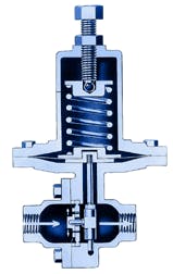
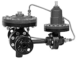
Shown here is a typical pilot-operated valve.
If flow demands are relatively constant, or if a 10 percent to 20 percent deviation from the set point is tolerable, a self-contained regulator should be used. If the fluctuations are great or accuracy is essential, pilot-operated valves or instruments might be necessary.
When selecting a valve for a pressure-reducing application, plants should keep in mind that:
A piloted regulator will exhibit less droop than a nonpiloted regulator.
Air-loaded regulators are much more accurate because the spring is eliminated.
High-flow regulators are less accurate than standard regulators.
Typically, the shorter the overall stroke, the less the droop.
Larger diaphragms will increase overall accuracy.
Regulators supplying a medium to multiple users/vessels will be less accurate than regulators supplying a medium to a single unit/vessel.
The set point should be toward the high end of the selected spring range to give increased regulation accuracy. CP
Gainer works for Jordan Valve, a div. of Richards Industries, Cincinnati. Contact him at [email protected].
Note: Photos courtesy of Jordan Valve.
