Heat exchanger efficiency is crucial. Fortunately, the chemical industry is benefiting from improvements as equipment makers such as Alfa Laval, Klaren International and Heatric leverage the latest materials and technologies to boost performance.
Five main factors — energy efficiency, capacity, emissions, water use and uptime — drive the chemical industry’s demand for improved heat exchanger technology today, says Gert Ternström, market development manager, petrochemical industry, Alfa Laval, Lund, Sweden.
“The overall focus is very much on process optimization and here compact heat exchangers offer great benefits,” he stresses.
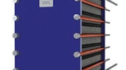
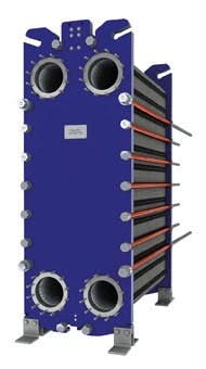
Figure 1. Wide distance between plates in compact exchanger enable it to handle thick, dirty fluids. Source: Alfa Laval.
The company’s Compabloc range exemplifies this, he notes. The all-welded plate pack eliminates gaskets between plates and makes it possible to operate with a wide range of aggressive media and at high temperatures and pressures.
Balaji Amines, Tamalwadi, India, certainly has benefited. It installed 48 Compablocs on its amine production plant, resulting in a 40% reduction in overall steam use, says the chemical maker.
“It seemed risky at the time because Compabloc was more expensive than alternative products,” notes Prathap Reddy, chairman and managing director of the Indian company. “But I’m happy we took the risk. The first installation of eight Compablocs laid the foundation for savings of around $700,000 per year. The Compabloc is a reliable and efficient product. Furthermore, it can withstand aggressive media and high temperature and pressure. It is also almost maintenance-free and can be cleaned in a few hours instead of days, two more advantages over shell-and-tube models.” Reddy adds the payback period for a Compabloc is shorter because of the huge energy savings achieved — and the company is well on the way to replacing all of its old shell-and-tube exchangers with Alfa Laval’s technology.
Ternström also highlights a project with a major paraxylene producer in Asia that has a 500,000-mt/y plant. The company decided to replace its existing air-cooled heat exchangers used for condensing overhead vapors from three of the plant’s columns with four Compablocs. Two were installed on top of the paraxylene recovery column and are now recovering 20 MW of waste heat, resulting in annual fuel savings of roughly €2.3 million ($2.6 million). The other two, which are installed on top of the recycle and de-heptanizer columns in the xylenes isomerization area, recover 3.7 MW, leading to roughly €430,000 ($482,000) in fuel savings per year. The payback time for the revamp, including the cost for installation, was less than one year.
However, despite these successes, Ternström says there’s still a lot of resistance to compact heat exchanger technology — despite a number of companies standardizing on it for specific activities such as absorption systems for gas sweetening and carbon dioxide removal from ethylene oxide processes.
“Other users are not so technology focused, so we are still only scratching the surface of what compact heat exchangers can be used for,” he explains.
Part of the challenge is to get plant designers to stop falling back on old rules-of-thumb about how much heat can be recovered using standard shell-and-tube exchangers. “They simply don’t take advantage of the huge potential benefits of using compact heat exchangers,” he laments.
One chemical company that is more proactive in this regard is BASF. Its Ludwigshafen, Germany, site has more Alfa Laval compact heat exchangers — about 1,500 — than any other chemical complex in the world.
The Swedish company has been working on a two-part strategy at Ludwigshafen’s acetylene and naphthalene plants. The first is to swap out compact gasketed plate-and-frame heat exchangers that posed a safety risk and led to frequent production stops with equally compact units without gaskets. The second is replace carbon steel shell-and-tube heat exchangers suffering from erosion.
To date, the benefits of this strategy include savings of €300,000–€400,000/y ($336,000–$448,000/y), two-thirds of which comes from eliminating leaky gaskets and the rest from maintenance savings, says BASF. There’s also a huge reduction in the amount of floor space, foundations, piping and installation work needed for the new heat exchangers.
“The Compablocs were around 25% lower in cost compared to retubing the existing shell-and-tube heat exchang¬ers,” says Frank Steiglich, project operation manager acetylene, at BASF, “On top of that, a lot of space was freed up, which resulted in a safer plant for the operators.”
Boiling and condensing operations generally have the potential for large savings, Ternström counsels. He cites reboilers as a bastion of conservative design that demands a rethink: “The higher efficiency of the compact plate technology opens up the use of lower temperature/quality heat sources. For example, doing the same boiling duty but replacing high-pressure steam with medium-pressure steam often results in 30–50% lower operating costs.”
Alfa Laval now is planning to develop even larger compact exchangers.
Combating Clogging
One of the company’s key development focuses is on designing models that can withstand a wider range of throughput, temperatures and pressures. This is illustrated by the company’s latest release, in May, of the WideGap 100 compact, gasketed plate heat exchanger (Figure 1). The wide distance between its plates makes the unit less susceptible to clogging. A special herringbone corrugation pattern of the plates causes high turbulence, which not only further helps reduce fouling but also increases heat transfer. The exchanger is aimed particularly at heating, cooling and heat recovery duties where thick, dirty fluids can cause clogging, for example during the manufacture of ethanol and bio-based chemicals.
Avoiding clogging also was the driving force behind the development of self-cleaning fluidized-bed heat exchange technology by Klaren International, Barneveld, The Netherlands. The operating principle of its self-cleaning exchangers is straightforward: recirculating particles scour the surface of the tubes to remove deposits as they form.
The fouling liquid passes upward through a vertical shell-and-tube exchanger that incorporates specially designed inlet and outlet channels. The particles (which consist of cut metal wire or glass or ceramic balls with diameters varying from 1–4 mm) also are fed at the inlet, where a distribution system ensures uniform flow of the liquid and suspended particles throughout the internal surface of the bundle. The particles, transported by the upward flow of liquid, create a mild scraping effect on the wall of the heat exchanger tubes. The particles disengage from the liquid at the top of the unit and are returned to the inlet channel through an external downcomer.
The process liquid fed to the exchanger is divided into a main flow and a secondary flow that transports the particles into the exchanger. Varying the secondary flow enables control of the amount of particles in the tubes and, thus, the cleaning effect. Particle circulation can be either continuous or intermittent.
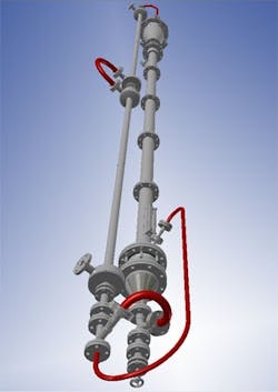
Figure 2. Single tube and downcomer provide critical data for design of full-size exchanger. Source: Klaren International.
In theory, any self-cleaning heat exchanger can be designed for zero fouling of the heat transfer surface by ensuring the rate of fouling removal by the scouring action of the particles exceeds the rate of fouling formation.
“As every process is different and thus the fouling phenomenon is difficult to define, describe and control, and correlations for the heat transfer film coefficients in the tubes (i.e., at the fluidized bed side) are difficult to determine for a circulating fluidized bed, the only option is an experiment with a representative test heat exchanger operating under the representative process conditions for the planned full-size fluidized-bed heat exchanger. Initially, such a test heat exchanger consisted of seven tubes of the same diameter and length as planned for the full-size heat exchanger and one external downcomer,” says Puneet Kedia, a process and development engineer at Klaren.
However, with operating pressures, temperatures and materials of construction varying from heat exchanger to heat exchanger, constructing test units that can mimic each one can be prohibitively expensive. So, Klaren has designed a more compact and affordable test unit that consists of only one tube in a shell and one downcomer (Figure 2).
The advantage of this test unit is that it can operate on a small liquid flow (which often is all that’s available), uses different sizes and types of particles, and enables independent variation of both the liquid mass flow and particle mass flow. So, it can generate an array of data with respect to the overall heat transfer coefficient and the fouling behavior of the system.
“This is important information we need for the design of any full-size heat exchanger and with this test heat exchanger configuration we will be able to generate all these important data with a low cost system, where even the heat exchange section (i.e., the tube in its shell) can be made at low cost for different shell-side media, such as condensing steam, liquid and even hot gases,” notes Kedia.
He believes this test unit will show that a self-cleaning fluidized-bed heat exchanger can guarantee zero fouling of heat transfer surfaces in contact with the fluidized particles.
Etched Plates
Heatric, Poole, U.K., focuses on printed circuit heat exchanger (PCHE) technology. Its exchangers are manufactured by a process called diffusion bonding that creates an exchanger core with no joints, welds or points of failure. The company says this results in a strong, highly efficient unit up to 85% smaller and lighter than traditional technologies such as shell-and-tube exchangers.
The PCHE cores used for heat exchange are constructed from flat metal plates into which fluid flow channels are chemically etched. These etched plates are then stacked and diffusion bonded, converting the plates into a solid metal block containing precisely engineered fluid flow passages.
Etching a network of fluid distributor channels into the plates enables staged reactants’ addition and mixing. These channels perform passage-by-passage mixing of process fluids and uniformly distribute process streams into catalyst beds, says the company.
Up until now, Heatric has focused mainly on the upstream hydrocarbon processing, petrochemical and refining industries, and counts companies such as Petrobras, BP, Shell and ExxonMobil among its customers.
However, the company now has its sights on the chemical industry and already has been working with a number of partners, gaining broad expertise in chemical reactor applications including the development of multiple adiabatic bed (MAB) reactors and compact steam reformers. Its MAB PCR (printed circuit reactor) effectively separates the functions of heat transfer and chemical reaction, allowing each to be optimized independently with no compromises or conflicts between chemical reaction and heat transfer requirements, claims the firm.
Industrial bulk chemical production, modular plants and micro-reactors are all potential uses in the chemical industry, says the company.


