Steam turbines extract thermal energy from pressurized steam and deliver mechanical work by rotating output shafts. These turbo-machines often are good choices to drive compressors, pumps, electrical generators and other equipment.
Steam turbines come in a wide array of designs and complexities to match the desired application and performance specifications. For industrial services, units may have a single casing or multiple casings (e.g., three — low, medium and high pressure).
Steam turbines are expensive to make, requiring precision manufacture and special quality materials, but generally provide long service lives, often exceeding 40 years. They are inherently rugged, reliable and low-maintenance drivers. Moreover, the turbines are easy to control and offer enclosed non-sparking operation suitable for some explosive atmospheres or corrosive environments. The units provide fast, reliable starting capability and are particularly adaptable for direct connection to driven equipment (such as compressors, pumps, etc.) that rotate at high speeds. Steam turbine drives can handle continuous duty under severe operating conditions. Their reliability and availability records usually are excellent; many steam turbines experience only one shutdown every 3–6 years.
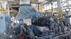
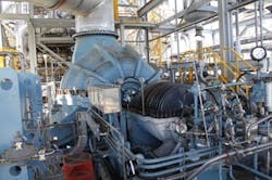
Figure 1. This steam turbine drives a large gas blower.
The Basics
A steam turbine is a form of heat engine that derives much of its improvement in thermodynamic efficiency from the use of multiple stages in the expansion of steam, which results in a closer approach to the ideal reversible expansion process. However, no steam turbine affords a truly isentropic or constant entropy process; typical isentropic efficiencies range from 70–91% based on the particular application.
The steam turbine operates on basic principles of thermodynamics using a portion of the Rankine cycle. Steam, which could be a superheated vapor or dry saturated vapor (depending upon application), enters the turbine at high temperature and high pressure. It encounters several sets of blades, or buckets as they are called in the steam turbine industry, which convert the energy of the steam into kinetic energy. One set of stationary blades is connected to the casing and one set of rotating blades is connected to the shaft. The sets intermesh with certain minimum clearances, with the size and configuration of sets varying to efficiently exploit the expansion of steam at each stage. The fluid exits the turbine as a low-energy steam (which could be nearly saturated vapor or a liquid/vapor mix depending upon application) at a lower temperature and pressure than it entered; the discharged fluid often goes to a condenser for cooling.
Except for low-power applications, turbine blades are arranged in multiple axial stages (in series), a technique called compounding, which greatly improves efficiency at part-load operation (low speeds). A significant advantage of steam turbines is their variable-speed and variable-load capabilities; such flexibility is extremely important in many applications, particularly variable-speed mechanical drive services such as compressors or pumps.
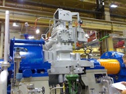
Figure 2. This unit is the driver of a large compressor train.
An impulse steam turbine has fixed nozzles that orient the steam flow into high-speed jets. These jets contain significant kinetic energy, which is converted into shaft rotation by bucket-like shaped rotor blades, as the steam jet changes direction. A pressure drop only occurs across the stationary blades (nozzles), with a net increase in steam velocity across the stage. As the steam flows through the nozzle, its pressure falls. Due to the relatively high ratio of expansion of steam, the steam leaves the nozzle with a relatively high velocity. Impulse steam turbines are also known as constant-pressure turbines.
In a reaction steam turbine, the rotor blades themselves are arranged to form convergent nozzles. This type of turbine makes use of the reaction force produced as the steam accelerates through the nozzles formed by the rotor. Steam is directed onto the rotor by the fixed vanes of a stator; it leaves the stator as a jet that fills the entire circumference of the rotor. The steam then changes direction and increases its speed relative to that of the blades. A pressure drop occurs across both the stator and the rotor, with steam accelerating through the stator and decelerating through the rotor, with no net change in steam velocity across the stage but with a decrease in both pressure and temperature, reflecting the work performed in the driving of the rotor.
The rotor blades of the reaction turbine are shaped more like aerofoils, arranged such that the cross-section of the chambers formed between the fixed blades diminishes from the inlet side toward the exhaust side of the blades. The chambers between the rotor blades essentially form nozzles so that as steam progresses through the chambers its velocity increases while at the same time its pressure decreases, just as in the nozzles formed by the fixed blades. Thus, the pressure falls in both the fixed and moving blades. As the steam emerges in a jet from between the rotor blades, it creates a reactive force on the blades that, in turn, causes the turning moment on the turbine rotor.
Most steam turbines use a mixture of reaction and impulse designs; each stage behaves as either one or the other but the overall steam turbine uses both.
Traditionally, multi-stage turbines featured one or more velocity-compounded impulse stages at the beginning (where the steam pressure is the highest) followed by reaction stages. This was more efficient with high-pressure steam due to reduced leakage between the turbine rotor and the casing. The sequence usually differs in many modern turbines; most often, higher-pressure sections are reaction type and lower-pressure stages are impulse type.
Steam Turbine Types
Considering the steam supply and exhaust conditions, machines can be classified as “condensing,” “non-condensing,” “reheat,” “extraction” and “induction” types. Condensing steam turbines most commonly are found in applications such as very large mechanical drive services or substantial power generation units (a steam turbine coupled to a large electrical generator). These steam turbines exhaust steam in a partially condensed state, typically of a quality near 90%, at a pressure well below atmospheric to a condenser.
Non-condensing or back-pressure steam turbines serve most frequently in mechanical drive applications such as medium-size drivers for pumps and compressors (Figures 1 and 2). A regulating valve controls the exhaust pressure to suit the needs of the process steam pressure. These machines also are used where large amounts of low-pressure steam are needed, to convert high-pressure steam to low-pressure steam.
Reheat turbines appear in sophisticated plants such as closely optimized mechanical drive units with steam production systems or combined-cycle power generation units. In a reheat steam turbine, steam flow exits from a high-pressure section of the turbine and returns to the steam generation system where more superheat is added. The steam then goes back into an intermediate-pressure section of the steam turbine and continues its expansion. Using reheat in a steam cycle increases the work output from the turbine; also the expansion concludes before the steam condenses, thereby minimizing the erosion of the blades in last rows of the turbine. Most cases use just a single reheat. Often no more than two reheats make sense because the cost of superheating the steam negates the increase in work output from the turbine.
Extraction steam turbines suit applications needing extracting steam. In these units, which boast theoretical high performance, steam is released from one or various stages of the turbine and used for process needs or sent to heaters, other auxiliary boiler(s) or waste-heat-recovery systems to improve overall cycle efficiency. Generally a valve controls extraction flow; in rare cases, the flow is left uncontrolled. Usually extraction-type steam turbines can make a chemical processing facility very complex. Properly controlling all variable parameters for such a complex system often is very difficult. In other words, managing a variable-speed mechanical-drive extracting-type steam turbine and variable extraction steam flow(s) simultaneously is tough.
Induction steam turbines introduce low-pressure steam at an intermediate stage to produce additional power.
My experience suggests minimizing the application of extraction and induction steam turbines.
Reliability And Maintenance
The high pressures used in the steam circuits mandate thick casings, which, in turn, give the steam turbine high thermal inertia that demands special attention. When warming up the machine for operation, the main steam stop valves have a bypass line to allow superheated steam to slowly bypass the valve and proceed to heat up the lines in the system along with the steam turbine. Also, when there is no major steam flow, a turning gear mechanism or similar system slowly rotates the turbine to ensure even heating to prevent uneven expansion. After first rotating a steam turbine by the turning gear, it is necessary to allow time for the rotor to assume a straight plane (no bowing), then the steam is admitted to the turbine, first to the astern blades then to the ahead blades, rotating the turbine at low speed (say, 10–20 rpm) to slowly warm the machine. The warm-up procedure for a large steam turbine may take 5–8 hours.
During normal operation, rotor imbalance can lead to vibration, which, because of the high speed, could result in a blade breaking away from the rotor and piercing the casing. To reduce this risk, considerable efforts are necessary to balance a steam turbine. Also, the units require high-quality steam, most often superheated (dry) steam or sometimes saturated steam with a high dryness. This averts erosion of the blades, which occurs when condensed water (moisture carryover) impinges on them. Also, liquid water entering the blades may damage the thrust bearings. Preventing this demands not only controls and baffles in the steam generation system to ensure high quality steam but also installation of condensate drains in the steam piping leading to the turbine.
As already noted, the operational life of a modern steam turbine often exceeds 40 years. Maintenance requirements of such units are simple and incur low costs. As a very rough indication, the maintenance cost could be around $0.004 per kWh. For instance, in a large plant with nine steam turbines and combined steam turbine mechanical power of about 75 MW, the annual maintenance cost could be around $2.6 million, which is lower than the maintenance costs associated with other driver types.
Speed Control
Safe and reliable operation depends upon proper speed control and protection. Use of a governor and other control and protection systems is essential, as steam turbines must be run within some speed limits, especially below a high-speed limit, to prevent damage or operational problems. Some applications, such as the generation of electricity, require precise speed control. Many mechanical drive services also are variable-speed applications and need fine control of speed. Uncontrolled acceleration of the steam turbine rotor can lead to an overspeed trip. If the speed control and trip system fail, then the steam turbine may continue accelerating until it breaks apart, often catastrophically.
Electric power generation units need precise speed adjustment. For instance, during normal operation in synchronization with the plant electricity network, steam-turbine-drive power units are governed with a 4 or 5% speed-control precision. This means the full load speed is 100% of the nominal speed and the nearly-no-load speed is 104% of the nominal speed. This is required for the stable operation of the electric network without hunting and dropouts of power units. Normally, changes in speed are minor. An old-fashion centrifugal governor or a modern electronic governor adjusts power output. Some variable-speed mechanical drive applications such as those for compressors or pumps often call for more-or-less the same precision of speed control.
AMIN ALMASI is a rotating equipment consultant based in Sydney, Australia. E-mail him at [email protected]
