Many companies today strive to achieve energy savings not just to enhance their bottom line but also to decrease their environmental footprint. Organizations handling powders and other bulk solids sometimes struggle to find obvious ways to improve their environmental footprint, evaluate the impact of changes or build viable investment proposals aimed at energy savings.
This article reviews possibilities for energy savings in the operation and design of powder handling processes. It focuses on common unit operations present in most bulk solids processes — pneumatic conveying, pulse-jet filtration and mixing — and gives examples to show how to calculate savings. Hopefully, this will help you assess the order of magnitude of the gain that you can expect, and guide you in building a case with management to implement the changes required.
Pneumatic Conveying
Companies often rely on pneumatic conveying — either dilute-phase or dense-phase — to transport materials between unit operations. Such conveying can accommodate all sorts of layouts and provides good containment of the solids. Both types of pneumatic conveying usually offer opportunities for energy savings.
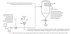
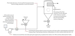
Dilute-phase conveying, in which solids are suspended in the transport air (Figure 1), is very common because it is quite simple to design and operate. The air mover generally is a Roots-type blower that can be positioned either at the beginning of the line (pressure dilute phase) or at the end of the line (vacuum dilute phase).
Figure 1. A number of ways to save energy usually are possible in such systems.
Experience shows that plant operators place most importance on avoiding line blockages and achieving a defined throughput. They, therefore, are tempted to select an over-sized blower and run it at high speed, which appears to them as being safer (but, in reality, is not quite true). Those blowers have motors drawing several kW.
An engineer looking for energy savings should calculate the air velocity in the conveying pipe and the solids loading ratio. Typically, a dilute-phase conveying line has a speed of 20–30 m/s at the end of the line and a solids loading ratio of around 5–10:1. If the values calculated for the line significantly differ, with a higher conveying speed and a lower solids loading ratio, then reducing the blower speed possibly may save energy. Organize a trial (always perform a risk analysis first) with the help of a pneumatic conveying expert to find the optimum conveying parameters.
As an example, let’s consider a blower used to convey 4.5 t/h of a product in a plant experiencing high breakage of the product.
Current conditions:
• Blower operates at 100%.
• The performance datasheet of the blower indicates >520 mbarg discharge pressure, an air flow of 1,066 Nm3/h (or 1.3 t/h) and a power on the shaft of 20.6 kW.
• This gives an air velocity at product pickup of 29.4 m/s at the discharge conditions of the blower.
• The solids air ratio is 4.5/1.3 = 3.45:1.
Usually, required pickup velocity is around 16–20 m/s. (It can be determined by experience or estimated thanks to correlations calculating the saltation velocity.) The solids load ratio for dilute-phase conveying can be between 5 and 10. Because the blower has a variable frequency drive, the engineer advises a trial to run the blower slower, targeting 20 m/s at the beginning of the line.
New conditions:
• Blower operates at 66%, discharging around 700 Nm3/h (0.86 t/h) of air.
• The trial shows a pressure drop of 400 mbarg. Using performance data of the blower, the power on the shaft for this speed and pressure is calculated as 11 kW.
• Solids load ratio is 4.5/0.91 = 4.95:1.
• The pressure is stable.
Continuing to run at those conditions will provide a significant savings. You can calculate the amount based on line’s annual running time, the difference in power and the cost per kWh. In this case, (8,000 h/y)×(20.6-11)×(US$0.10/kWh) = US$7,680/y.
Note that optimizing the air velocity also brings advantages in quality and maintenance by reducing material attrition during transport and decreasing pipe wear.
Dense-Phase Pressure Conveying
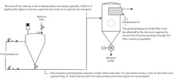
Here, compressed air pressurizing blow tanks and the conveying line transports the solids (Figure 2). Compressed air is expensive to produce, so any over-consumption quickly will cost a substantial amount of money.
It always makes sense to check the conveying parameters and, especially, to calculate the mass air flowrate actually used to transport material. Such systems should be designed to convey at low velocity, typically 3–8 m/s, and high solids load ratio, usually >30:1. Determining that the air velocity is significantly higher and the solids load ratio is significantly lower than these values indicates likely room for improvement. Getting into the right conveying regime will reduce the air consumption and generate savings.
Figure 2. These systems typically offer several energy-saving opportunities.
Let’s consider the case of a line conveying 4.5 t/h of product and using around 350 Nm3/h (or 430 kg/h) of air. An engineer studying the process trends realizes the pressure is quite low and, so, calculates the solids load ratio.
Current condition:
• Solids load ratio = 4,500/430 = 10.5:1.
This is a low solids load ratio; the conveying probably is not dense phase. The engineer consults an available report on pilot plant tests and finds this product can convey at a ratio of 30:1.
New conditions:
• Solids load ratio = 30:1.
• Air conveying flowrate for that ratio = 4,500/(30×1.225) = 122.5 Nm3/h.
The engineer organizes a test, adjusting the timers for opening the different air valves in the system to obtain a stable pressure. The pressure is higher, because more material is in the line, but dense-phase conveying takes place.
Under the new conditions, the line consumes 227.5 Nm3/h less compressed air. Given the factory’s cost for compressed air of US$0.01/Nm3 and the line’s operation for 4,000 h/y (for batch conveying), the savings amount to 227.5×4,000×US$0.01 = US$9,100.
You should design dense-phase conveying systems to avoid strong line flush at the end of a transfer. Eliminating, when possible, such operation from the conveying sequence also can lead to savings.
Filters
Many filters feature a compressed-air pulse jet system to unclog them. This is particularly so in the case of filters located at receivers of conveying lines, which usually are quite large (several m2). Very often, a timer governs the operation of the pulse jet system. Improper timer settings can waste compressed air.
For such filters, pulsing every 30 s. to 1 min. usually is a good starting point that can be refined by monitoring the pressure drop through the filter and adjusting accordingly. Also, there is no need to run the back-flush of the filter for long after the conveying has ended. Because of all the filters usually present in a process, potential savings often significantly exceed what plant owners expect.
Consider a small (6-m2) filter that has a pulse jet system equipped with a 10-L air tank compressed at 3 barg for cleaning the filter. The filter is cleaned every 15 s.
Current conditions:
• Interval between pulses = 15 s.
• Air consumption/h = 3,600/15×3×10 = 7,200 L/h = 7.2 Nm3/h.
Because the dust load is low, the engineer explores changing the interval between pulses to 1 min.
New conditions:
• Interval between pulses = 1 min.
• Air consumption/h = 3,600/60×3×10 = 1,800 L/h = 1.8 Nm3/h.
The line operates for 8,000 h/y, so this saves (7.2-1.8)×8,000 = 43,200 Nm3/y. Given the factory’s cost for compressed air of US$0.01/Nm3, the savings for this one filter amount to US$432/y. Considering the many such filters in the plant, total annual savings can add up to hundreds or even thousands of dollars. This also depends on the size of the filters because large normal filters can have a compressed air manifold of up to 30:l.
Batch Mixing
Mixers usually come equipped with motors drawing several kW. Optimizing the mixing process won’t always yield large cuts in energy consumption but will help establish a mindset that, applied to the whole solids-handling process line, will contribute positively to cost savings and environmental care.
You should aim to optimize the mixing time so the mixer’s motor runs only when needed. Batch mixers often operate far longer than required. Carrying out a proper mixing validation will help define the minimum mixing time necessary to reach the desired target homogeneity. Saving 1–5 min./batch can count when a mixer operates frequently.
Consider a plant with a double-shaft paddle mixer equipped with a 15-kW motor.
Current condition:
• Total mixing time = 4 min.
Double-shaft paddle mixers usually are designed for a 1–2-min. mixing time. So, the engineer carries out a new validation of the homogeneity; it shows that the mixture reaches the homogeneity target after mixing for 2 min.
New condition:
• Total mixing time = 2 min.
This mixer handles 10 batches/h and runs 5,000 h/y (because of downtime needed for changeovers, etc.). It now consumes 10×5,000×(2/60)×15 = 25,000 kWh/y. The plant pays US$0.10/kWh, so the saving is US$2,500/y.
However, this savings usually is not the primary benefit of optimizing the cycle time of the mixer. More significant savings generally accrue from increasing the production capacity, thus reducing the cost of production and potentially avoiding the need to invest in new equipment.
Design
Even better environmental and economic results can come from considering energy savings at the design stage. Keep the following pointers in mind:
• Design a simple layout for the pneumatic conveying line; additional length and bends cause extra pressure drop and, therefore, require more energy.
• Determine experimentally the minimum conveying velocity of the material to be transported. As shown, a velocity higher than required will lead to substantial energy overspending.
• Control the design margins used by vendors; for instance, blowers sometimes are over-sized.
• Do not automatically position an aftercooler after a blower in pressure dilute-phase conveying; you may not need such a unit. Only install an aftercooler if it is proven that the system or the product cannot stand the temperature increase due to the blower compression.
• For dense-phase operation, carry out experimental trials to design the line so it can convey at the highest possible solids load ratio.
• Design the automation system to keep a line from running without product. Use a timer to switch off the line after a certain time not handling material.
• When possible, take advantage of gravity to move powders and, so, reduce the use of pneumatic (or mechanical) conveying.
• Ensure, when possible, treated air is not lost but recycled.
Designing a process to be energy efficient is an essential initial step. However, over the long term, savings will materialize through rigorous maintenance of the process equipment. This is particularly true for compressed air consumption because a pressure regulator easily can be set improperly or a solenoid can fail with time, leading to increased consumption.
Operators should check all compressed air settings on a regular basis, at least weekly. These regular inspections also provide the opportunity to spot compressed air leaks that happen from time to time at fittings and that can be very costly if not immediately addressed.
Make Solid Progress
This article has looked at only some of the many sources of energy savings possible in a bulk handling process. Remember that while individual savings may not be great, by taking a systematic approach you can achieve a cumulative impact that significantly improves the competitiveness of a process. Providing proper instrumentation and maintenance will ensure that an installation performs close to its energy optimum and will help develop environmental consciousness within your company.
THOMAS LAMOTTE is a senior process engineer at Nestlé Research & Development Singapore. Email him at [email protected].


