The hopper at an Egyptian fertilizer plant caused erratic flow and bridging, disrupting production. The hopper receives phosphate powder from a milling process via a pneumatic conveyor. Feed from the silo must be regulated so that the acidulation process can be correctly proportioned; an unpredictable feed rate makes the process very difficult, if not impossible, to control.
The plant experienced flow problems shortly after start-up with material hang-ups and occasional flushing. Its process equipment supplier, Bradley Pulverizer, installed aeration pads in the hopper to blow low volume air into the powder to encourage material flow. However, this resulted in more uncontrollable flow and flooding of downstream equipment.
The flow regime generated in the hopper, so-called funnel flow, exacerbated the problem. This type of flow arises when the converging wall inclination is too shallow to induce the contents at the walls to slip as the hopper empties. A narrow flow path forms from the outlet to the surface, creating a “last-in, first out” phenomenon, so freshly milled material comes out first; original fill material may remain against the walls for a long time, deteriorating in flowability.
In response, in 2016, Bradley Pulverizer asked Ajax Equipment to find a way to improve flow. Ajax determined the fix was to convert the hopper flow regime to mass flow. This would ensure all hopper contents moved together during discharge so that “first in” material is “first out” and would avoid extended storage time of some of the contents.
Finding The Culprits
A common approach to predicting powder flow behavior is to use a single number as a guide. However, this approach is fraught with problems. For example, there’s no obvious reason why a powder with high friction properties also should have a strong cohesive tendency or vice versa; while the situation for flow may worsen when both these attributes are present, they aren’t necessarily correlated.
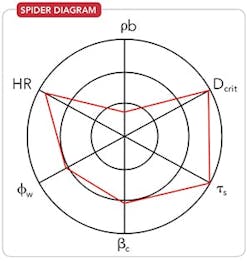
A better approach to predicting flow behavior is to use the measured characteristics of wall friction (φ w), shear strength (τ s) and bulk density (ρ b) along with three further factors: hopper or reactor wall angle (β c), outlet size (Dcrit) and Hausner ratio (HR), which is the ratio of tapped to loose bulk density. (As the HR increases, the powder becomes more sensitive to vibration and, hence, its flowability worsens.) These factors enable producing a “spider” diagram comprising a series of three concentric circles divided by axes for each of the characteristics. The smallest diameter circle shows the specific values of the characteristics that provide “easy flow” while the larger diameter circles define “modest” and “poor flow,” respectively. This allows presenting idealized situations for an “easy flow” material and a “poor flow” one with the in-filled part of the “web” detailing the particular characterization attributes.
Spider web diagrams can provide more than a qualitative indication if you can use data from tests on a large number of materials to define the “easy,” “modest” and “poor” flow circles.
Figure 1. High values for shear strength and wall friction angle mandate steep hopper walls and a large outlet for reliable flow.
Note that the bulk density axis is the reverse of the others because decreasing bulk density usually means poorer flow. For example, most milling operations lower bulk density and worsen flowability of powders when they are stored.
Testing of the fine phosphate powder revealed that the powder flow properties, together with variability in the composition, residence time and consolidating pressures in the silo, caused the problem. The measured flow properties and calculated hopper parameters were:
• bulk density, ρ b, 989 kg/m3;
• critical diameter, Dcrit, 102 cm;
• shear strength, τ s, 3,574 N/m3;
• hopper wall angle, β c, 69°;
• wall friction angle, φ w, 21.9°; and
• Hausner ratio, HR, 1.47.
A spider diagram (Figure 1) of the phosphate powder identified high shear strength and wall friction values that demand steep hopper walls and large outlet sizes for reliable flow.
Wall friction testing allowed Ajax to determine the hopper wall inclination needed for mass flow; it would increase residence time in the hopper and enhance de-aeration. The wall friction measurements also identified significant slip benefits with 2B finish stainless steel over the existing mild steel surface.
The Solution
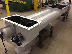
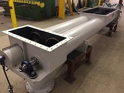
Because converting the entire hopper to mass flow would have been expensive, Ajax proposed replacing a 2-m-deep bottom section of the hopper with a vee-shaped section to exploit plane flow benefits and a large outlet fitted with a twin-screw feeder of special extraction geometry (Figure 2) to draw from the full width and length of the new hopper bottom. Another proposed alteration was incorporating a flow insert to enhance de-aeration and extend the flow benefits into the unaltered higher region of the hopper. These changes would result in a more-even residence time of the contents and a large reduction in the flow velocity (spread over a wider area) to further favor de-aeration. Moreover, the minimal plant modifications would ensure reliable operating performance.
Figure 2. Unit features special extraction geometry and draws from the full width and length of the new hopper bottom.
It only took five months from quote to delivery and installation of the equipment in Egypt.
A careful re-commissioning process was enabled progressively assessing each section of the retrofit. The changes resulted in steady and reliable flow without arching or flushing and created a consistent feed stream for subsequent plant operations.
A large proportion of the previously static hopper contents now flows during discharge. A further benefit of fitting the insert is that it prevents a direct flow path and forces material to draw from the peripheral areas near the walls with even shallower wall angles than required for a conventional mass-flow hopper. This results in increased working storage capacity and a more-uniform residence time and stable reliable flow. Indeed, the feed rate variation has decreased from more than 30% before the modifications to better than 0.5%. This means that the acidulation process can be carried out properly.
“Since the equipment has been installed, the performance of the process has significantly improved. By providing complete control over the flow of phosphate powder, Ajax’s equipment has enabled production of the high-quality product desired, a welcome improvement to plant performance and ‘the magic solution’ according to the plant operator,” comments Ian Hancock, operations manager at Bradley Pulverizer.
Table 1. Tests conducted for thesis [1] led to these recommended values.
Eddie McGee is managing director of Ajax Equipment, Ltd., Bolton, U.K. Email him at [email protected].
REFERENCE
1. McGee, E., “An Investigation into Characterisation of Bulk Solids and Flow in Hoppers,” Ph.D. thesis, Glasgow Caledonian University, Glasgow (2005).


