Combustible dust can pose a hidden hazard when accumulation occurs in unseen locations such as in mechanical spaces, above false ceiling, ventilation systems and dust collection systems. Such hazards may be particularly well hidden in certain pharmaceutical manufacturing facilities where use of clean rooms with surrounding mechanical areas are common and the scale of the equipment and facility is relatively modest. Even small quantities of combustible dust may result in a dust cloud flash fire or an explosion capable of significant damage in a plant environment. Although events of this magnitude may not make headline news, the potential impact on an individual present during a flash fire could be life changing.
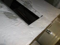
Figure 1. Inspection revealed that interior of dust collector contained an accumulation ½- to 1-in. thick.
[javascriptSnippet ]
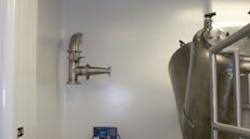
This example comes from a pharmaceutical blending operation located in a typical clean room. Technicians are preparing to blend 110 kg of dried pharmaceutical powder. All surfaces within the room are dust free and the polished stainless steel blender has just been cleaned. The technicians connect a small 2-in. ventilation trunk between the blender and a port on the clean room wall labeled “to dust collector.” The technicians then open the access cover of the blender and press a button to start the dust collector, which is located elsewhere. Seven bags, each containing 16 kg of dried powder, are charged to the blender through the opening. The technicians are wearing personal protective equipment (PPE) to prevent inhalation of the dust but no dust is observed outside the opening. When the product charge is completed, technicians turn off the dust collector and disconnect the 2-in. ventilation trunk. The trunk is visually clean. The self-contained blending operation completes normally. All equipment and the room itself then are cleaned in preparation for the next batch. Lastly, the technicians leave the clean room to check for accumulation of material in a small drum under the dust collector; the drum is empty as always. The technicians know the routine well; they have completed these tasks at least once a week for the last ten years.
By their training, the technicians understand the powder they are handling is a combustible dust. They know the minimum ignition energy (MIE) has been tested at approximately 200 mJ with an average particle size of 27 microns, which means the risk of ignition from an electrostatic discharge from personnel is greatly reduced, and personnel grounding isn’t required [1]. The electrical outlets and switches in the clean room look different from others in the area, and signs hang on the doors indicating the room is electrically classified as Class II, Division II for combustible dust. If technicians observe a dust cloud for any reason (e.g., a dropped product bag), they are to immediately leave the area until the cloud settles. In general, technicians believe little if any dusting occurs during loading of product to the blender — a belief supported by the lack of dusting seen during blender loading and emptying the dust collector discharge drum.
The technicians and technical support personnel assumed that because no dust is coming out of the dust collector, no dust is going in. The assumption was widely believed to be true and even documented in a previously completed formal hazard review. The idea that dust accumulation might be possible simply did not occur to those supporting the blending operation.
A TELLING INSPECTION
In 2012, the facility initiated a hazard review process for all solids handled at the site. This included looking specifically at the dust accumulation risk for each operation. One recommendation stemming from this activity was for engineering to perform an internal inspection of the blending operation dust collector.
Prior to the inspection, the team reviewed available design information for the dust collector and field-verified all ductwork. The system was designed for an airflow of 500 ft3/min to ensure sufficient capture velocity at the blender opening during loading. The ductwork in the field begins at the clean room wall, where the duct diameter increases from 2 in. to 4 in. and then transitions to a diameter of 6 in. immediately prior to a 15-ft vertical riser. The duct then travels horizontally several hundred feet through multiple mechanical rooms before reaching the dust collector inlet plenum. Portions of this ductwork run above false ceilings. At the inlet plenum, the 6-in. duct expands to a 1-ft × 3-ft rectangle at which point it enters the dust collector. That unit, which is 1 ft in diameter and 3 ft in length, contains four cartridge filters. The dust collector is equipped with a differential-pressure pulsation system to clear the filters under conditions of high pressure drop. At the bottom of the dust collector, a manual slide gate valve leads to the aforementioned drum for dust disposal.
During the engineering inspection, the four cartridge filters were removed and found to be heavily loaded with dust. Internal inspection of the dust collector revealed ½-in.+ layers of dust settled on all horizontal surfaces including the inlet plenum (Figure 1). Samples were taken and submitted for particle-size and MIE testing. The average particle size of the material in the dust collector was 12 microns, half the size of the bulk powder loaded to the blender. That in itself isn’t surprising because the dust collector air stream primarily captures fines churned up during blender loading. The MIE for the material in the dust collector was approximately 25 mJ — an order of magnitude less than that of the bulk powder loaded into the blender! With an MIE as low as 25 mJ, the risk of ignition from electrostatic discharges becomes a greater hazard, necessitating enhanced safeguards including personnel grounding [1].
Upon discovery of this fine collected dust, planning commenced for its removal. Engineering personnel led the effort and got assistance from maintenance and operations. The cleaning scope included both the main body of the dust collector and all impacted ductwork. Engineering developed a written cleaning plan. A hazard review team then performed a risk analysis of the proposal. Hazard review teams are routine at this facility due to the significant quantities of solvents utilized. However, site personnel were relatively inexperienced with combustible dust remediation. To ensure a robust review, corporate combustible-dust subject matter experts and the contractors selected to perform the cleaning joined site engineering, operations, maintenance and health/safety personnel to perform a what-if risk analysis of the written cleaning plan.
Using photographs from the field, engineering went over the entire dust collection system with the review team. The MIE data obtained for the dust then were used to list types of ignition sources that would have sufficient energy to ignite a dust cloud if one formed during the cleaning operation. The hazard review team next focused on two specific areas for risk reduction: 1) identifying safeguards that would prevent/minimize/contain disruption of the dust to prevent formation of a combustible dust cloud during cleaning; and 2) identifying safeguards to minimize all possible ignition sources in the event a combustible dust cloud inadvertently was created.
To minimize the risk of creating a dust cloud, the cleaning plan incorporated multiple recommendations from the hazard review team. First, the order of line breaks and cleaning activities were specified so as to remove dust from easy-to-access areas prior to performing higher-risk line breaks. The goal was to remove as much fuel from the system as possible before performing overhead work with reduced egress options. This included removal of the filter elements and cleaning of the dust collector prior to disassembling overhead ductwork. Second, extra ductwork supports were installed. Adding these supports ensured the ductwork couldn’t accidently fall as it was disassembled, disturbing settled dust and potentially forming an ignitable dust cloud. Third, plastic sheeting and glove bags (similar to those used for asbestos remediation) isolated rooms and line breaks. These actions ensured that any dust disturbed wouldn’t be able to travel outside the boundaries of the work area, where measures to enhance protection against ignition also were being put in place.
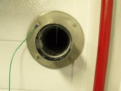
Figure 2. Ground wire was installed to prevent isolation of metal during cleaning of 4-in. duct.
Potential ignition sources were categorized, e.g., charge on metal surfaces (scaffolding, ductwork, etc), charge on personnel, charge on tools, the vacuum to be used for cleaning, and surrounding electrical equipment. Again, the cleaning plan incorporated multiple recommendations from the hazard review team. Grounding wires were installed in multiple predefined locations including the ductwork (Figure 2), dust collector, scaffolding and any other potentially isolated metal surface. Engineering inspected the contractor air-powered HEPA vacuum equipment. Prior to the cleaning, which took place in August 2013, all operating equipment in the work area was shut down, and an extensive lock-out/tag-out was performed for all electrically powered equipment. Lock out of electrical equipment was accomplished remotely in motor control centers or at electric breaker panels away from the work area. Equipment locked out included motors, heaters, power outlets and control panels. Immediately prior to performing work, engineering met with contractors and maintenance personnel to review the cleaning plan, PPE requirements, and combustible dust hazards. All personnel were instructed to leave the area in the event of a dust cloud. “Danger” tape isolated the entire area; technicians posted at all entrances kept personnel out of the cleaning area.The planning and coordination for the cleaning activity took several weeks but the cleaning itself required less than six hours. Approximately 10 kg of combustible dust were removed from the system and collected as a wet paste in the bottom of the contractor’s vacuum equipment. After cleaning, engineering inspected all ductwork, which was in like-new condition.PREVENTING FUTURE PROBLEMSEngineering initiated a root cause investigation into why dust had accumulated and what needed to be implemented to stop accumulation from occurring in the future. The root cause investigation identified two causal factors. First, designers had inaccurate/incomplete process safety information when the dust collection system was installed over a decade prior to this event. Preliminary design documentation erroneously indicated the product wasn’t combustible. As a result, the dust collector system design didn’t incorporate standards applicable to combustible dust (isolation/suppression systems, housekeeping program, etc.). Second, multiple opportunities to identify the risk of accumulating material were missed even after the material was confirmed to be combustible. One opportunity came after several years of service when an initial combustible-dust hazard assessment was completed on the blending operation/dust collector. At the time, the facility had minimal organizational knowledge regarding combustible dust hazards. Technicians interviewed then stated that little dusting occurred during loading of the blender and no dust ever was discharged from the dust collector. These types of observations prompted the review team to conclude that no dust was being pulled into the dust collector system. The root cause investigation found these observations/conclusions to be inaccurate. The lack of dusting at the blender was due to the successful operation of the dust collector (i.e., dust is pulled away from the operator as intended). The failure to discharge material from the dust collector was traced to a mechanical problem with the internal pulsation system, which likely never had functioned following initial installation. This explained the heavy loading seen on the filters. Another opportunity to recognize that dust was accumulating arose during completion of routine airflow testing. The investigation found that a 50% drop in airflow was documented in the work history of the dust collector but not flagged as a potential dust-collector operations issue. The reduced airflow rate of 250 ft3/min sufficed to maintain operator protection from an industrial hygiene perspective, so no actions were taken to restore the airflow to the original design requirement of 500 ft3/min. The reduced flow and, thus, duct velocity accelerated accumulation. Generally, preventing the settling of materials similar to this product requires a minimum airflow rate of 2,500 ft/min [2]. At 250 ft3/min, the dust collector system was operating well below this minimum velocity in the 6-in.-diameter line that accounted for the majority of the ductwork in the system. In some cases, nearly 50% of the duct cross-sectional area was found to be plugged, particularly near the bottom of vertical risers where dust settling was prevalent.Recommendations from the root cause investigation included: upgrading the system design to be suitable for combustible dust service; implementing routine internal inspections; establishing pass/fail criteria for duct velocity measurements; modifying duct sizing to increase airflow velocity; and setting up a program for regular internal cleaning.The key takeaways from our experience are: • Accurate material properties are essential for making informed risk-based decisions whenever handling combustible dust. The properties of a specific combustible dust material can vary greatly with changes in particle size. In our case, a 50% reduction in particle size resulted in an order-of-magnitude decrease in MIE and, thus, a far greater risk of a combustible dust flash-fire/explosion. Failure to understand this reduction in MIE might have resulted in less-stringent safeguards during development of the cleaning plan.• Having all affected parties and subject matter experts take part in performing a thorough hazard analysis is invaluable in confirming that a written plan provides the safest possible path forward for executing a non-routine activity.• An effective prework safety meeting ensures work is completed in the manner intended by the hazard review team and also provides a final opportunity to address concerns of those performing the work. In the end, a significant amount of resources went into the uneventful cleaning of a small quantity of accumulated material. The results of the cleaning activity and subsequent investigation were communicated in multiple forums across the organization. Many committed team members actively participated in completing this work. Hopefully, this simple example results in positive outcomes for others vigilantly working to reduce combustible dust risk.
CYRUS FISHER is a consultant engineer for Eli Lilly and Company, Indianapolis, IN. E-mail him at [email protected].
REFERENCES
1. “NFPA 77 – Recommended Practice on Static Electricity,” 2014 ed., National Fire Protection Assn., Quincy, MA (2013).
2. “Industrial Ventilation,” 25th ed., American Conf. of Governmental Industrial Hygienists, Cincinnati, OH (2004).


