I cannot tell you how many manufacturing facilities currently have tank systems with load cells installed that is no longer operational. Most of the times the load cells are left in place and the electrical cables connecting to the controls are simply cut. Production managers, quality control managers, and maintenance engineers alike have encountered weigh cells that never worked properly. Why? Why have so many switched from a supposedly high accuracy load cell solution to old fashioned level probes or sight glasses? There are several causes. I will touch on the worst culprits.
The design
OK, I am an engineer and I must admit before I specialized in load cell solutions I couldnt care less what type of load cell was specified under a tank during project design phase. I would pick a load cell from the local catalog; mount one cell under each leg bingo, a perfect weighing system. The only science involved was finding the vessel dead-weight, estimating the product specific gravity, and then calculating the total weight. It was an easy design, simple integration drawings, then it was time to move on: Westinghouse engineering. Make it fit, then plug it in.
Poor specification of load cell systems may not be engineering incompetence. Rather, it could be a lack of education of how load cells work and a lack of appreciation of how real life factors affect these installations. A review of some simple mechanics, installation tips, and a few real life lessons found in this article may help design engineers more effectively integrate load cells. Quality control managers, production managers and others also may gain some insight into correcting their existing tank or hopper installations.
Understand the mechanics
The heart of the weigh cell is the strain gauge. Although there are several different types of weigh cells, I will focus on the shear beam load cell. The alignment of the force vectors is important; these sensors cannot discriminate against true vertical load and side/torque loading. You want to measure the true vertical load, i.e., the weight within the tank not the shear loads. However, real world conditions or improper installation often cause the load cells to see much more than vertical loading. These other factors are what cause poor repeatability in weighing that ultimately lead to abandonment of load systems. Before learning about the factors that cause inaccurate tank weighing it is important to learn how a shear beam actually works.
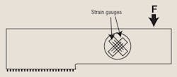
A shear beam load cell is a precision-milled piece of metal that includes several strain gauges. These gauges are positioned at a 45° angles to measure the steel shear strain.
Figure 1 shows the principle positioning of the strain gauges on the shear beam load cell.
Figure 1. The shear beam weigh cell is highly dependent on the material of construction.
Strain gauges are zigzag-shaped strip conductors, etched from thin metal film. They operate on the principle that the electrical resistance of a conductor will increase when it is subjected to mechanical stress. This mechanical stress is caused by tiny changes in the film length and cross-section. The resulting voltage change is very slight; to measure it accurately, a Wheatstone bridge or some other familiar amplifying circuit is used. The letter F in Figure 1 shows how force is introduced to the shear beam cell.
The body of the load cell is usually constructed of mild steel, stainless steel alloy or aluminum. A typical load cell will undergo thousands of weighing cycles, so the composition of the metal is very critical in producing reproducible weighing results. A shear beam load cell is actually measuring the shear strain of steel, so if the steel itself isnt monolithic throughout, errors in weighing will occur. Metal selection also affects the life cycle of the cell; body failures have occurred. In general, its critical that load cell manufacturer obtain steel and aluminum that is high grade to produce the most reliable installation.
Not all cells are the same
Bending beam and shear beam load cells are the industry standard for bench and floor scales. Next time you have a free moment, lift up the pan and look underneath a scale. More than likely, you will find some type of bending beam load cell. If these types of load cells are used in bench scales then why cant they be used in vessel weighing tasks?
Scales and balances are self-contained units that rarely encounter the extraneous side forces and environmental influences that vessels do. Yes, it is true that scales are subject to environmental factors, however not to the extent of process vessels. Bending beam load cells are perfect for environments where static weighing take place; they arent intended for a process vessel. Weighing a vessel requires a load cell and mechanical support system with a high tolerance of non-vertical loading and a capability for producing reproducible measurements.
Start with the tank
First things first, a weighing application will never be successful without proper attention to the tank. Vessels are usually designed to safely hold a quantity of material accounting for such factors as wind, earthquakes and other forces of nature. The idea that the vessel will need to weigh a material is generally an afterthought in its design.
The most important factor to consider when designing for a weigh cell is the construction of the weighing frame. The frame is where the load cells will be mounted. Whether the cell is a shear beam, bending beam or compression type does not matter. This structural steel is mechanically connected to all the load cells under the vessel to ensure that they cannot move in different directions independently of each other. Because were only interested in vertical compression forces the design must resist external forces that could cause the load cells to tilt.
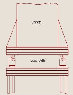
Figure 2 shows the best type of installation. Notice how the load cells are placed in the middle of the beams. Each cell is situated between two frames. This frame network ensures the load cells will move together, creating a more repeatable weighing environment.
Figure 2. Constructing a rigid frame is critical for repeatable weighing.
In Figure 2 the load cells are mounted on top of a bottom frame assembly that provides a rigid foundation. The weight of the vessel is being transferred to the load cells and then to the bottom frame. This transfer of force occurs with minimal deflection. Although the load cells can be mounted directly to the floor without the bottom frame, the floor must allow little deflection and settling. The load cells are measuring deflection down to thousands of a millimeter, so if your foundation deflects, you arent going to achieve acceptable accuracy. Most architectural designs allow a floor deflection that would be unacceptable for weigh cell operation.
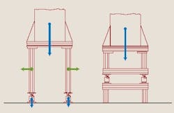
Figure 3 illustrates another typical design problem found in tank weighing. It shows load cells installed on the end of very long tank legs. In this example, errors are due to the legs moving in different directions. Measurements become unrepeatable as extraneous deflection causes variability in movement.
Figure 3. Shortening the span between the tank base and the weigh cells reduces the bending moment causing poor repeatability and inaccuracy.
The second drawing in Figure 3 illustrates a good load cells installation; the legs from the tank are shorter, minimizing separate leg movement, and the load cell has a top and bottom frame to help induce a more uniform loading pattern. These figures show a common error; each weighing applications is different.
Rigid tank construction with a solid foundation, top/bottom frame, short legs got it. What other tank design factors must be considered? One of the most overlooked factors is the vessels peripheral connections and accessories, such as pipes, mixers, ladders, walkways, etc. Each of these external fixtures influences the weighing system. This is another reason why design of a process and the vessel should be included when considering load cells.
Pipes entering and exiting a vessel are always exerting forces on it. Under stable, ambient conditions, e.g., constant temperature, pipes and nozzles dont create serious problems for weigh cells. We all know that industrial applications are far from ambient. Thermal expansion and movement will adversely affect weighing results. To better visualize this effect simply stand on your bathroom scale and take your weight reading (dont worry I dont like what my scale reads either!) Next weigh yourself by gently pushing on the wall, and then once more by pulling on a nearby towel rack. The results are different arent they? This type of action/reaction force is similar on vessel weighing applications where pipes are present.
Figure 4 illustrates the possible forces and displacements of piping: a rigid pipe can lift some weight off the vessel and cause a displacement (dP). A force Fp along the pipe can push the vessel to the side and exert forces downward or vise versa.
Figure 4. The pipe force (Fp) added to the vessel appears as a false low weight at the weigh cells.
By carefully considering pipe supports and nozzle design, it may be possible to reduce pipe problems. A simple way to dampen the effects of pipes on weighing measurements is to have all pipe connections enter from the side. If possible, place pipe hangers as far away from the tank as possible to allow for flexing as the tank moves up and down during loading. Rollers may help but they will eventually fail and cause problems. Some movement can always be expected. Flexible pipe connections and bellows may be the best solution. These connectors should lessen some of the influence of pipe forces on the vessel and moderate pipe fatigue. However, ensure the flexible connections are truly flexible. A 1-in. flex joint on a 4-in. pipe probably isnt effective against either pipe fatigue or weigh cell interference.
Installation
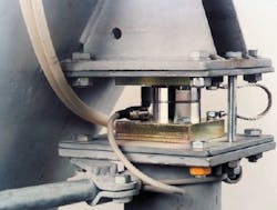
Once you ensure that your tank is properly designed and all pipe connections are flexible, the next step is to select the correct weighing system. Although shear beams and bending beams can be used, I suggest compression-type load cells. Unlike shear-beam or bending beam, compression load cells are designed to eliminate the introduction of non-vertical loads. This is accomplished by carefully engineering a curved top and bottom. These rounded components allow the cells to right themselves during side loading by a principle of restoring forces (Figure 5).
Figure 5. Heat shield protects a 20,000 kg compression load cell and mounting hardware.
Compression cells, like those pictured in Figure 6, are designed to shift during vessel expansion and are constrained mechanically to eliminate the influences of other non-vertical forces.
Figure 6. Compression weigh cells are generally the choice for resisting influence of non-vertical forces.
A compression load cell shouldnt be bolted to the floor or to sub-framing like typical beam load cells. All external forces, including from mixers and thermal expansion, cannot be isolated from beam-type load cells. The interference from these forces can be effectively eliminated with the proper installation of compression cells.
One of the tools available with compression cells is the mechanical restraint. Mechanical restraints are simple devices though they are capable of taking care of most complex side loading influences when used properly. These devices are generally installed on the sides of the load-cell mounting kits. They are similar in many ways to classic turnbuckle assemblies. These turnbuckle assemblies absorb non-vertical forces from direct side loading, e.g., wind, and torque forces created from vertically-mounted mixers.
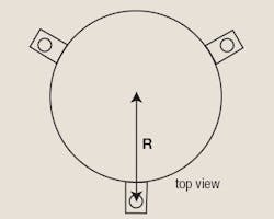
Figure 7 is a typical compression-cell mounting kit with an integrated turnbuckle.
Figure 7. The proper installation for turnbuckles assures equal weight distribution between weigh cells.
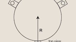
Mounting kits only perform well if aligned correctly to absorb side forces. Figure 7 illustrates how to properly install mounting kits in both three-legged and four-legged vessels. As you can see, the turnbuckle assemblies are tangential to the tank in three-leg applications. The four-legged installation is usually more stable than the three-legged system. This type of turnbuckle arrangement is used to absorb torque forces from mixers and distribute side forces equally among the constrainers. Mounts in the four-leg tanks are installed so that no one turnbuckle points toward another. This configuration is necessary to avoid unnecessary axial binding. In this way, each turnbuckle shares the load equally across the entire base of the vessel.
Lets consider one final issue: thermal expansion of the tank. Thermal expansion and contraction occurs for a variety of different reasons, the most common being: jacket heating or cooling, environmental or diurnal temperature changes, and the addition of hot or cold fluids to the vessel. Were a shear beam or bending beam to be used there would be no physical way to prevent vessel expansion or contraction from inducing a load on the cells.
For example, with this type of installation, heating would cause the vessel walls to press outward on the load cells. Stress would create a force vector in the downward direction, registering as a weight change on the cells. This expansion will cause drastic, unrepeatable, weight changes from a few pounds or kilograms up to hundreds of kilograms.
Consider Figure 8, a stainless steel vessel of AISI304/1.4301 material.
Figure 8. A 230°C temperature change causes a significant change in the weigh cell reading.
The weigh system is calibrated under ambient conditions (20°C) but operated at a temperature of 250°C when the jacket heating system is running. The engineering calculations are presented below:
Radius of the tank (R) = 1.25 m
Expansion coefficient (k) = 1.6 mm/m/100°K (different depending on material!)
Temperature Difference = 250°C 20°C = 230°C
Strain (ΣT) = 1.6mm/m × 230°C/100°K = 3.68 mm/m
Expansion of the radius = 1.25 meters × 3.68 mm/m = 4.6 mm
The expansion of the tank 4.6 mm in a shear beam weighing applications will produce severe weighing errors. Compression load cells are not physically bolted to the floor, but rather are floating and allowed to shift slightly when the tank expands. This type of cell, if properly installed, avoids the inaccuracies of thermal expansion.
Some homemade remedies have been tried to compensate for thermal expansion. Blowing cool air on load cells, wrapping insulation around load cells, or dowsing cells with water are not adequate solutions for the effects of tank expansion on load cells. Installing load cells that can mechanically expand with the vessel and, secondly, ameliorating the influence of external side forces are the best solutions (Figure 9).
Money talks
No matter the industry, weighing accuracy equals money, and in most cases it equals lots of money. Operating a plant with vessels that dont weigh properly can cost time and plant efficiency, which equates to a cost. Inaccurate tank weighing can literally cost thousands of dollars in lost product and wasted time. It is critical to consult with an experienced tank weighing company, familiar with not just load cell specifications, but also the engineering behind the system.
Ryan Titmas is a product manager at Sartorius North America in Edgewood, N.Y.; e-mail him at [email protected].
