1660329003121 Cp0604 Solids F1 Web

Install pneumatic conveyors correctly

March 7, 2006
Follow these 10 tips to prevent a variety of common problems that could occur with your pneumatic conveyors.

Pneumatic conveying is one of the most versatile ways to move solids over moderate distances. So, not surprisingly, Chemical Processing over the years has published a number of articles (e.g., Ref. 1) on the design, installation and operation of dense- and dilute-phase pneumatic conveyors. Several models and a whole host of data from research groups also are available. However, even the best model and data can only go so far. Actual performance depends upon mechanical accuracy. For instance, a small unnoticed leak can kill the performance of a pneumatic conveyor — so much for having a good model.

Additional problems may result from non-uniformity of the flow or local changes in the solids-to-air ratio.

The reality of most plant environments is that the quest to keep costs low can dictate design considerations and spell trouble, particularly when using old equipment for a new project.

However, you can take a number of steps to prevent problems.

Top 10 tips

I have found the following pointers useful both for planning new systems and modifying existing ones.

  • Put lifts before horizontal runs. In most conveyors the feed point has the lowest gas velocity and particles may fall out of suspension. This can be offset by line size changes but standard line sizes can force you to push the velocity higher than desired, especially near the end of the line. As the pressure along the line goes down, the velocity goes up. By raising the conveyor in front of horizontal runs instead of at the end, particles have a chance to accelerate toward the gas velocity and gain momentum, mainly because the choking velocity is generally lower than the saltation velocity. The downside is cost. Unless you are going over a building, the extra support can be expensive.
  • Minimize elbows and angled runs. Pressure drop and attrition are highest in elbows (for the effective distance solids travel). Most of the wear and maintenance seen in pneumatic conveyors is due to the elbows; so it often is best not to use too many. The major exception to minimizing the number of elbows in a system is for a line that needs to go up and then horizontal. While an angled run offers the shortest distance between two points, it does not have lowest pressure drop. Indeed, a convey line going up at a 45° angle has much higher pressure drop than a horizontal and vertical line with three elbows. Putting elbows too close together is another major mistake, due to acceleration effects. Many models just count the amount of elbows — but placement in the layout is more important. The lowest number of elbows is not always optimum.
  • Calculate velocity every 10 to 20 feet on the line. Don’t rely only on measurements of the pickup velocity or the maximum and minimum velocities in the system. The velocity of the gas and particulates should be determined along the entire length of the line, to ensure that the correct density is used to determine the choking and saltation velocities. This makes the design a trial-and-error calculation. Shortcut design methods often overlook this critical step.
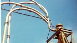
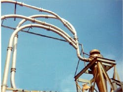
  • Check acceleration lengths at feeders and around elbows. It takes time for a particle to reach its slip velocity (effective velocity below the gas velocity). Particles also must be dispersed across the convey line so the solids-to-air ratio is uniform — otherwise the saltation effects will be drastically different. You could have high localized solids-to-air ratios that would throw a dilute-phase conveyor into dense phase and slug flow. The acceleration length can be determined using the graphic technique of Rose and Duckworth [2] or the Jotaki and Tomita method [3]. For a quick estimate of the optimal spacing of elbows or feeders from each other, use a value between the square root and the cube root of the stopping distance for the particle in feet: Xs = (Vg dp2ρs)/(18μg)where Vg is gas velocity, ft/s; dp is particle diameter, ft; ρs is effective particle density, lb/ft3; and μg is gas viscosity, lb/ft-s. Sometimes it is obvious by looking at a conveying line that the elbows are too close together and the layout was not well planned (e.g., Figure 1).
    Figure 1. Sometimes no detailed analysis is needed to spot a bad layout.
  • Be careful with pipe joints. Piping should be carefully aligned during installation. The use of slip-couplings can allow for gaps or pinched gaskets, even with tie-bars. Even welded pipe can be improperly fabricated at the flange due to misalignment and “cat teeth” from the welds. When joining pipe, specialized welding methods can prevent slag inside the pipe.
  • Slow the particles down before the collector. Particle-to-particle impact is the biggest source of attrition. Even discharge into a bin can result in a significant amount of attrition as the particles strike the pile. Bag collectors increase the particle-to-particle contact unless there is a cyclonic inlet or an expansion of the line prior to the collector. The acceleration velocity can be used to judge the length of any deceleration spool piece, generally about 25% of the acceleration length, or the optimal distance between elbows, as described in Tip 4.
  • Watch for leaks. Small leaks can cripple operation by reducing or increasing the difference between the gas and saltation velocity. High velocities lead to high pressure drop and attrition; low velocities lead to transitional flow (dilute to dense). The obvious location of a leak is at the feeder. When several feeders are on the same convey line, check for leakage at each one. Diverters and misaligned pipe also can contribute to the problem. In vacuum systems, the area around the collector, including the discharge valve, can be a major leak source.
  • Match the type of compressor to your convey line. On most dilute conveyors the pressure rises rapidly during the feeding of solids and usually falls off after leaks and the compressor slip have stabilized. A large surge tank can help but adds cost to the system. Volumetric feeders are just that — the solids-to-air ratio will vary over a conveying cycle. As the compressor heats up, the gas velocity can increase in small or light-weight compressors, leading to attrition of the solids. When a conveying system is used continuously, this usually is not a problem, except maybe during start-up. Oversized compressors that run at low speeds can be sluggish and unable to keep up with leaks or sudden changes in solids-to-air ratio. This is especially true when re-using spare equipment.
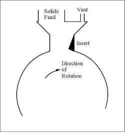
  • Vent the feeder valves and factor the amount lost into the design. If there is one thing that can upset a pneumatic conveyor it’s sudden changes in solids-to-air ratio. An unvented solids feeder prevents the pockets from filling uniformly and can fluidize the solids in the tank or bin above the feeder. The solids can flood the valve, prompting over-consolidation and bridging. Not only does the solids-to-air ratio change but particles also can be pinched in the feeder and break. Figure 2 shows a way to vent the valve in the absence of a vent port supplied by the manufacturer. Note the use of an insert to prevent particles being pinched between the housing and rotor.
    Figure 2. This modification enables venting if a valve lacks a vent port.
  • Look for frictional differences between products. Sometimes after conveying one material and either making a change to the ingredients or trying to convey a different material we forget that the particles may not behave the same. While basic physical properties can be helpful in predicting a problem you can’t go wrong with a few tests. Frictional changes can be subtle. Even the same product can have different shear rates and pickup velocities. In addition, don’t forget to check the characteristics of an existing material after conveying a new material. A fine coating or change in surface may alter the pressure drop in the system.
  • Running a convey test

    One of the most important parts of putting in a new conveying line is correct testing, especially on a new product or long layout. Most equipment manufacturers will perform a test for a nominal fee that seldom covers its real cost. Remember vendors are not clairvoyant and usually don’t understand your overall process as well as you do. Some engineers arrive at a test expecting the manufacturer to guide them through the testing process and to point out what the buyer needs to do. That approach doesn’t sell a lot of pneumatic conveyors, which after all is the vendor’s objective. Most manufacturers’ test setups are not research systems but demonstration devices. So, it is best to have a test plan that you and the vendor agreed upon beforehand. This may mean bringing in additional testing resources at your cost to supplement what is provided.

    Pointers

    1. Look at particle attrition. Conduct particle sizing tests and examine the particles under a microscope.
    2. Attempt to find the choking and saltation velocities. Compare these to calculated values. Design the system at 1.5 times the maximum value but plan to reduce this velocity after installation (by reducing the blower flow rate).
    3. Run at both twice and half of the expected design velocity.
    4. Ensure the solids-to-air ratio is constant during the test.
    5. Calculate velocity along the line. This requires data on pressure and temperature.
    6. Roughly determine the particle-to-gas velocity along a straight section of pipe.
    7. Get the layout close to what is expected in the plant. Try to match elbows and lift location.
    8. Make some of your own measurements. This keeps the vendor honest.
    9. Inspect the piping. Pay attention to the type of joints, construction material, elbow R/D, feeder and collector details.
    10. Run a “power failure” test. Deliberately stop the gas flow and let the line sit overnight, if possible. Failures happen. The best place to find out their consequences is in the lab.

    While following the test and designing the conveyor, enjoy the process of understanding your material. Imagine yourself running around inside the pipe. Pneumatic conveyors are powerful and the solids convey considerable force. I was reminded of that one time when every few hours we heard a clanking noise in a vertical section on a recirculation pneumatic conveying blender. We shut down the conveyor and removed the bottom elbow to find a 6-in.-long, 1-in.-diameter bolt that had made several trips through the system. Oh well!

    References

    1. Haraburda, S.S., “7 steps to efficient conveying,” Chemical Processing, Vol. 63 (2), p. 57 (February 2000). 2. Duckworth, R.A. and H.E. Rose, “Transport of Solid Particles in Liquid and Gases,” Engineer, Vol. 227 (5,905), pp. 392-396, 430-433 and 478-483, London (1969).3. Jotaki, Y. and Y. Tomita, “Flow in the Acceleration Region of Pneumatic Transport of Granular Solids in Vertical Pipes,” Proceedings of Pneumotransport 3, pp. 99-108, Bath, U.K. (April 1976).

    About the Author

    Tom Blackwood, Solids Advice columnist | Contributing Editor

    Tom Blackwood, a veteran engineer who has dealt extensively with solids over the course of his career, contributes regularly to Chemical Processing and serves as the Solid Advice columnist.

    Sponsored Recommendations

    Keys to Improving Safety in Chemical Processes (PDF)

    Many facilities handle dangerous processes and products on a daily basis. Keeping everything under control demands well-trained people working with the best equipment.

    Get Hands-On Training in Emerson's Interactive Plant Environment

    Enhance the training experience and increase retention by training hands-on in Emerson's Interactive Plant Environment. Build skills here so you have them where and when it matters...

    Rosemount™ 625IR Fixed Gas Detector (Video)

    See how Rosemount™ 625IR Fixed Gas Detector helps keep workers safe with ultra-fast response times to detect hydrocarbon gases before they can create dangerous situations.

    Micro Motion 4700 Coriolis Configurable Inputs and Outputs Transmitter

    The Micro Motion 4700 Coriolis Transmitter offers a compact C1D1 (Zone 1) housing. Bluetooth and Smart Meter Verification are available.