Process plants must operate securely as well as safely. Two international standards — International Electrotechnical Commission (IEC) 61508, which relates to functional safety, and IEC 62443, which addresses security challenges in automation systems — can help. An alignment project at the IEC describes how to apply the two standards simultaneously and defines three guiding principles. However, before examining these, let’s look at how security issues can impact functional safety in process plants to give context to the principles and clarify their role in implementing the new standard.
Some fundamental questions about the relationship between cybersecurity and plant safety arise. Can the vulnerability of integrated control systems influence a plant’s functional safety and, if so, what needs to be protected? More specifically, can we apply the principles developed for functional safety to information technology (IT) security?
[callToAction]
Before we can decide if a control system could pose a functional safety threat, we must define functional safety. For this, IEC 61508 provides valuable insight. According to that standard, functional safety is “part of the overall safety that depends on functional and physical units operating correctly in response to their inputs.”
This definition reveals the relationship between vulnerability and functional safety; incidents caused by malicious attack, design or operator faults that compromised functional safety attest to this relationship. The objective of IT security must be to protect operations from any possible negative influences, thereby eliminating, or at least minimizing, potential hazards to people, the environment and assets.
In terms of what needs to be protected, we must understand that, even without malicious threats, IT security vulnerabilities afflict almost every automation application. This includes the safety-related system itself and the distributed control system (DCS). Accordingly, many safety experts call not only for the physical separation of safety instrumented system (SIS) and DCS components but also for different engineering staffs or vendors to handle each. As we shall see, both safety and security standards encourage independence of control and safety functions.
Coordinated Strategy
Systems designers endeavoring to align security and safety also must decide which aspect has the highest priority. There’s no definitive answer to this question; safety and security experts alike tend to favor their own perspective. This is why experts in an IEC working group (TC 65 20.1) currently are developing a strategy that allows IEC 61508 safety concepts and IEC 62443 security concepts to be applied in harmony.
When designing integrated strategies, it’s essential to consider several aspects. First, a dedicated functional safety management system must serve as the baseline of all activities. Other aspects include avoidance of failures and maintenance of control if they do occur, reliability evaluations, and security. It’s also important to remember that safety and security focus on entirely distinct aspects; there’s no automatic correlation between functional safety and security.
The IEC working group is seeking to clarify a suitable strategic approach; its recommendations are being written up as IEC TS 63069, and comprise three working principles:
Principle 1: Protection of safety functions. The SIS should be protected from the consequences of security-related influences so the safety integrity of the SIS isn’t compromised.
This recommendation calls for adequate attention to security-related aspects to ensure they don’t negatively impact the SIS’s safety performance.
In practice, this means the residual risk borne by the security-related aspects mustn’t lead to a higher rate of dangerous failures than acceptable for the specific safety integrity level, e.g., one dangerous fault per 1,000 years of operation for SIL 3. This can be achieved by establishing and maintaining safety and security zones and conduits as described in IEC 62443-3-2.
Principle 2: Compatibility of implementations. During testing, any modification or change should undergo a safety impact analysis to determine all SIS components impacted and the necessary re-verification activities.
This recommendation means that every modification to a safety system must receive an impact review in combination with the necessary re-verification. A verification is a process during which the reality is checked against the design documents. Safety system verification usually can’t take place while the safety system is in operation.
So, if you implement a safety system needing regular patches (e.g., once a month/week), each of these patches requires the execution of the re-verification process. This testing conflicts with a requirement to operate a safety system for one year without interruption, for example.
Principle 3: Protection of security countermeasures. Design and development of safety functions should adhere to security coding and protection standards to minimize the introduction of vulnerabilities.
Exceptional situations such as emergency operation and proof-testing activities shouldn’t compromise security countermeasures by, for example, bringing in additional information systems such as notebook computers or portable memory devices that haven’t been through comprehensive measures and procedures to maintain the security settings applied.
Developing A Balanced Strategy
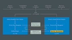
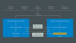
You first must perform an overall hazard and risk analysis. While human protection is the highest priority, safeguarding the environment, assets, information and business continuation also may impact the overall risk to be mitigated.
Figure. 1. Prospective countermeasures must satisfy both safety and security requirements.
As Figure 1 highlights, risk analysis results should go simultaneously to the team responsible for safety and the one handling security. Once set, the safety risk-mitigation concept passes to the security team. This triggers an interactive process to define all related security aspects required to protect the safety system.
The security risk mitigation process results in the definition of a security environment for functional safety agreed upon by both teams. The definitions of the security environment cover features to be implemented inside the components of the functional safety system (SIS) and other measures to comply with the security recommendations (e.g., added firewalls, etc.). Both the safety measures implemented and the related security measures get crosschecked for their compatibility as well as their maintainability throughout the entire safety lifecycle. This ensures the target risk reduction is maintained and that safety and security measures don’t negatively impact one another.
Any conflicts arising must be resolved; if resolution isn’t possible, external risk reduction measures must be defined.
Sufficient Separation
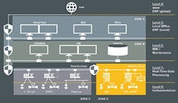
The already mentioned concept of zones and conduits (Figure 2) introduced by IEC 62443-3-2 can ensure a sufficient level of separation between the SIS and the basic process control system (BPCS).
A zone in this context is a dedicated part of an overall application where identical security recommendations apply. Each zone has clearly defined perimeters and dedicated interfaces to other zones or the Web.
Figure. 2. This approach can ensure sufficient separation between the safety and control systems.
The level of protection measures required for each zone must be specified to cover the individual recommendations defined by IEC 62443-3-3’s “Foundational Requirements,” namely:
1. Identification and authentication control;
2. Use control;
3. System integrity;
4. Data confidentiality;
5. Restricted data flow;
6. Timely response to events; and
7. Resource availability.
IEC 62433-3-3 focuses particularly on the so-called essential functions, those required to maintain health, safety, the environment and availability for the equipment under control.
In considering whether functional safety principles can be applied to IT security, it’s worth noting that both the IEC 61511 (safety) and IEC 62443 (security) standards demand independent protection layers. Each stipulates:
• Independence of control and safety;
• Measures to reduce systematic errors;
• Separation of technical and management responsibilities; and
• Reduction of common-cause failures.
The standards also highlight that the entire system is only as strong as its weakest link. When using integrated safety systems — that is, where the safety system and standard automation system are on the same platform — you should treat all hardware and software that could impair the safety function as part of the safety function. This means you must subject the standard automation system to the same management process as the safety system.
In addition, an implementation lacking independence between the BPCS and the SIS protection layer requires review for its risk reduction capabilities; these must be able to cover the overall risk reduction of the BPCS plus the SIS. Achieving SIL 2 (for safety) or higher might pose economic challenges because the common components of both, BPCS as well as SIS, need to comply with SIL 3 (in case of SIL 2 for safety).
The range of options for the security environment is wide.
For example, if all devices used for the safety application comply with required security measures, you may not need specific measures to protect the safety system perimeters. However, if individual devices lack security measures, you must cover all security risks though perimeter protection of the application.
Besides protecting the perimeters and the devices themselves, you must look at the interaction between different safety domain devices, including the communication infrastructure used, because these, if attacked, may cause denial of service or other security-related safety incidents.
This is very important for two reasons:
1. Parts of generic communication systems used for interconnecting functional safety components (e.g., multiplexers running multiple communication channels via the same media) must undergo the same security risk mitigation process as all other components involved in functional safety. Using only virtual network segregation won’t comply with the physical segregation required by IEC 61511.
2. When such devices are using encrypted data transition (e.g., VPN encryption), based on the usage of safe protocols as per IEC 61784-3, an interference might occur between the related fault modeling and the encryption. Such interference might lead to the situation that such transition may not be able to comply with the required fault behavior anymore.
Decoupling
Another consideration is the different time frames of the safety and security lifecycles. To prevent changes within the security lifecycle, such as during security patches for the safety system — impairing the safety lifecycle — you must decouple the two areas.
Decoupling involves:
• Segregating the devices that are part of the safety system from the rest; IEC 61508-1 chapter 7.6.2.7 gives guidance.
• Ensuring the devices inside the safety-security environment don’t need regular security patches, as these will necessitate a major testing effort. Per IEC 61511, all modifications leading to a change in the behavior of the SIS need verification; after being implemented, security patches potentially changing the timely behavior of the SIS likely will require testing on either the production system or a test system capable of fully checking all functionalities used.
• Verifying that the security environment hosting the safety system includes associated devices such as engineering stations and human/machine interface (HMI) stations with write access to the safety system. While you also may connect HMI stations outside the security zone of functional safety to the safety system, you must ensure that all potential transfer of inappropriate data from such stations to the SIS doesn’t lead to critical situations.
You also must consider practical aspects when setting up a secure environment for functional safety. For example, how can you make modifications securely? Operating systems such as Windows require occasional but ongoing updates and modifications. You could open a connection between an engineering station and the outer world, allowing these updates to be installed as needed. However, as experience across the industry has shown, this creates a door into the system that hackers are ready to exploit. Providing such a permanent door, even just for occasional use, probably isn’t worth the risk. Instead, transporting the updates using portable memories that have been checked to ensure they carry only data and no software functionality might be better.
The question of whether separate engineering workstations are truly necessary raises similar arguments. Virtualizing a set of stations onto one all-purpose machine might simplify the situation. However, if engineering workstations are moved outside the secure environment, the risk of creating a backdoor arises again.
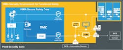
In theory, you could establish a perfectly secure environment by completely eliminating any communication between the safety system and the DCS. However, in the real world, some data exchange is essential; operating staff must be adequately informed about everything happening in their plant, for both safety and operational reasons. One option is to pass the data through an OPC server sandwiched between two firewalls, which together establish a barrier robust enough to withstand hacking attacks. This OPC arrangement also could handle communications between a HART asset management system and its field devices, thus allowing the security measures required to protect HART devices that contribute to SIS functionality.
Figure. 3. This secure system provides resilient communications as well as functionality that withstands cyberattacks.
If real-time data timing constraints make OPC topology impossible, you can opt for a bus like Modbus TCP instead. This will require several different safety precautions, starting with communications partner whitelisting (i.e., allowing only partners with recognized names and addresses to talk to the safety system). The system will block communication attempts from unauthorized addresses and raise an alarm to facilitate prompt investigation. More detailed safety precautions include different address areas per function, clear segregation of read/write, value check per variable, and performance monitoring per interface.
Safety system components must be able to communicate with the outside world. However, these communications channels must provide sufficient resilience. One example of a secure approach with resilient communications is HIMA’s Secure Safety Core (Figure 3). It enables components to maintain their design function even during or after potentially security-related attacks.
Take A Tandem Approach
Processors seeking to reap the benefits of connected systems must address the rising threat of cyberattacks. This calls for a specialized strategy that covers the different but interrelated issues of safety and security. Help is available in the form of IEC 61508 for safety and IEC 62443 for security, along with a strategy to apply these two standards simultaneously under the emerging IEC TS 63069 standard.
PETER SIEBER is vice president norms & standards for HIMA Paul Hildebrandt GmbH, Bruehl, Germany. Email him at [email protected].
