Fire ranks high on the list of costly risks to chemical plants, according to FM Global, a Johnston, R.I.-based business insurer. The risk of fire often stems from the chemical processes themselves, which frequently involve volatile and flammable materials. To protect workers, chemical plants must have life safety fire systems that detect combustible gases, smoke and flames as early as possible — and communicate detection information in real time to help prevent harm to personnel and property.
While the design and specification of fire and gas (F&G) safety systems require the involvement of experts in the field, some practical knowledge of the subject can help a chemical plant operator better understand the capabilities and necessary ongoing maintenance of its F&G system.
Here are seven tips to help plant personnel ensure their facility has adequate fire protection.
1. Identify Fire Hazards
Before designing and installing a fire protection system, it’s important to identify potential fire hazards within the facility by performing a fire hazard analysis (FHA). Chemical plants often conduct FHAs with the help of a consulting fire protection engineer.
An FHA seeks to determine the expected outcome triggered by a specific set of conditions called a fire scenario. FHA fire scenarios take into account building specifications such as room dimensions and contents, construction materials and potential sources of combustion.
Methods used to estimate the potential impact of fire scenarios fall into two categories: risk-based and hazard-based. Both approaches estimate the consequences of possible events. Risk-based methods evaluate the likelihood of different scenarios while hazard-based ones don’t.
2. Learn About Standards And Certifications
Another important preliminary step is reviewing applicable fire standards such as those from the National Fire Protection Association (NFPA), Quincy, Mass. In particular, chemical plant operators should check “NFPA 70 National Electrical Code” or “NEC (NFPA 70)” and “NFPA 72 National Fire Alarm and Signaling Code.” Chapter 17 of NFPA 72 lays out requirements for various types of devices usable to detect indications of fire.
These devices’ primary function is to detect a hazard and then signal to alert that an event has occurred. At the same time, it’s essential that detectors can maximize false alarm rejection so they don’t alarm to non-hazardous events. NFPA 72 defines a nuisance alarm as an “unwanted activation of a signaling system or an alarm initiating device in response to a stimulus or condition that is not the result of a potentially hazardous condition.” Nuisance alarms can be costly, causing unnecessary process stoppages that result in significant downtime, so proper device placement is important.
The surest way to know detectors meet safety standards, such as those in NFPA 70 and 72, is to specify equipment with certification documentation. Performance testing and certification verify that a device complies with application standards and will operate as specified by the manufacturer under a wide range of conditions. A vendor should be able to provide documentation of this independent product evaluation.
3. Consider Gas Detection First
Because they can alert chemical plant personnel to a gas leak before the gas ignites, combustible gas detectors are considered the first line of defense against destructive fires. NFPA 72 describes a gas detector as “a device that detects the presence of a specified gas concentration.” The gas detection system should give an early warning of both the presence and general location of an accumulation of flammable gas or vapor. In addition, advanced systems provide diagnostic functions, historical data logging and digital communications.
Common fixed gas-leak-detection technologies include:
Point detectors. Using electrochemical, catalytic or infrared (IR) technology, these devices provide gas concentration measurements when they come in contact with combustible gases.
Line-of -sight (LOS) detectors. These detect gas along a path between a transmitter and receiver, normally using IR technology.
Acoustic detectors. Such devices employ ultrasonic technology to detect gas leaks.
Chemical plants most often opt for catalytic and IR point gas sensors as these offer proven performance and reliability over years of use. IR sensor technology can’t detect hydrogen gas, so catalytic sensors are used in areas where explosive levels of hydrogen may occur. Catalytic and IR detectors typically can be fitted with weather shields or dust caps to protect the sensor and potentially lengthen intervals between maintenance.
Point detector technologies require gas to travel to the sensor; this can necessitate a large number of installation points and a robust placement strategy. Because the detector must come in contact with the gas or vapor cloud, you should locate it adjacent to the equipment being protected. In addition, when determining the proper placement and number of gas detectors required for adequate coverage, you must account for flow considerations from ventilation, fans, wind, convection, etc.
To ensure proper operation, you always should install point detectors in accordance with the manufacturer’s instruction manual. For detection of gases heavier than air, you should position point detectors below the level of exhaust ventilation openings and close to the floor. For detection of gases lighter than air, you should place the detector above the level of exhaust ventilation openings and close to the ceiling.
Because LOS systems can’t provide gas concentration measurements, they supplement rather than replace point detectors. While not recommended as the primary means of protecting equipment, LOS systems continuously monitor for the presence of combustible hydrocarbon gas. LOS features should include a wide alignment tolerance and failsafe operation as well as low maintenance and infrequent calibration requirements. LOS detectors also should withstand harsh conditions, including chemical exposure, precipitation and occasional vibration.
Figure 1. Device doesn’t require contact with gas yet provides fast response to pressurized gas leaks.
To consistently maintain optical alignment of the transmitter and receiver, you should mount LOS detectors to a rigid and stable surface. In addition, careful component placement is crucial because the system requires an unobstructed line of sight between the transmitter and receiver. However, typical LOS detectors are self-monitoring and will alert users should a blocked light beam or some other issue adversely affect detector operation.
Before operation, you should calibrate point detectors according to the manufacturer's instructions for the gas type(s) to be detected. Once in use, all point detectors require periodic recalibration using the appropriate calibration method. Regulations may specify the necessary calibration frequency; if not, consult the manufacturer’s documentation.
Where possible, you should install remote calibration-initiation and gas lines to simplify the task of calibrating difficult-to-access detectors. When feasible, you should place detectors in locations that aren’t too hard to reach.
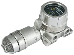
Unlike point and LOS technologies, both of which require gas plumes to move to active sensing regions, an acoustic leak detector (Figure 1) can respond almost immediately to a pressurized gas leak. Moreover, rain, wind, fog or obstructions may affect its detection capabilities less. However, acoustic detectors can’t distinguish between combustible and non-combustible gas leaks.
Because every gas detection technology has benefits and limitations, a common strategy is to combine the technologies and place each in locations that maximize their effectiveness. In many chemical plants, for example, LOS devices work with point detectors to provide optimal protection. In such situations, the point detectors are installed at or near high-risk gas leakage points or accumulation areas to provide gas level information. LOS detectors, on the other hand, often are placed at process unit or site boundaries where they can monitor the perimeter and track gas cloud movement into and out of an area.
As they age, some gas detectors can suffer degradation from dust, solvents and other contaminants in the air. Therefore, they require ongoing maintenance for proper operation and increased longevity. You should follow the specific maintenance instructions for the particular detection device as detailed in its product manual.
4. Use Industrial Smoke Detectors
While combustible gas detectors can warn of increased fire risk, smoke detectors pick up early indications that a fire actually has started. Smoke detectors used in hazardous locations differ from ordinary smoke detectors because they must be rated (either “explosion-proof” or “intrinsically safe”) for the risks associated with explosive substances.
Hazardous-area smoke detectors spot particles produced by combustion using a variety of technologies, including ionization, cloud chamber, photoelectric light obscuration, photoelectric light scattering and video image detection.
Before embarking on the design of a hazardous-area smoke detection system, you should review applicable standards such as “NFPA 92 Standard for Smoke Control Systems,” which addresses the design, installation, operation and testing of smoke control systems. For smoke detectors to be effective, you should locate and space them based on airflow from sources likely to present fire risks.
As with gas detectors, to simplify maintenance you should place smoke detectors in locations that aren’t too difficult to access. Also, you should keep smoke detectors as free as possible of dust, dirt and other substances that could impair their operation. Product manuals for particular models will specify any additional maintenance requirements.
5. Add Flame Detectors
No fire protection system is comprehensive without optical flame detectors to spot the radiant energy emitted by a flame. Flame detectors employ several sensing technologies, including ultraviolet (UV), IR, UV/IR and multi-spectrum IR (MSIR). When selecting from among these options, you must match the spectral response of the device to the spectral emissions of the fires to be detected.
Figure 2. Proper placement requires avoiding obstructions between detectors and the area of interest.
In addition, you can performance test a flame detector with the fire type to determine its effective detection range. Flame performance testing also can ascertain a detector’s coverage area or field of view (FOV). In most cases, the greater a detector’s range and FOV, the fewer devices a plant will need to achieve the necessary coverage. As with gas detectors, optical flame detectors require a clear line of sight to the area being protected, so proper placement, i.e., with no obstructions between detectors and the area of interest, is critical (Figure 2).
Because non-fire sources as well as fire emit UV and IR energy, it’s important that flame detection systems don’t misinterpret non-hazardous situations and set off costly false alarms. IR and MSIR detectors typically differentiate fire from non-fire sources by using optical filters and algorithms that analyze the characteristics of the IR energy detected. In most cases, such analysis can successfully identify non-fire IR sources. However, if an object or person moves between the non-fire IR source and the detector, the randomly modulated IR energy produced could mimic a fire signal.
To optimize a flame detector’s false-alarm-rejection performance, you should limit a detector’s FOV to the area that requires flame monitoring. In addition, controlling the detector’s FOV by careful installation and aiming will enhance performance. You also can consult the manufacturer for information about detector configurations that can help mitigate the effects of background IR sources.
An easy way to reduce false alarms is to remove sources of intense IR emissions, such as hot objects including fin-fan heat exchangers and hot pipes, from a flame detector’s FOV. When this isn’t possible, you should inhibit the operation of a flame detector that has an intense IR source within its FOV before personnel begin working near the detector.
Another way to minimize false alarms is to use multiple devices to monitor the same area to validate flame detection. This type of system must include algorithms capable of handling “voting” circuits (with each detector’s interpretation of an event counting as one vote) and making correct decisions based on input from multiple detectors.
6. Manage Communication And Response
A fire protection system must include a safety system controller (SSC) that receives and interprets inputs from multiple detectors and, as required, triggers notification and fire suppression. Look for an SSC that is third-party certified for applicable standards, including those dealing with performance and hazardous locations.
In chemical plants, the SSC provides information about detection device status to the process control system (PCS) to keep personnel overseeing operations informed of important fire-related events. In many cases, the PCS is configured to take actions that help mitigate and control a hazardous situation picked up by the fire system. Because the fire system and PCS are independent of each other, a PCS failure won’t affect fire protection functions.
7. Don’t Skimp On Fire Protection
As is the case when considering any new purchase, it’s natural to look for ways to reduce costs. However, always bear in mind that cutting the costs of fire protection may increase the risk to your facility and workers. It’s critical to follow applicable codes, standards and local regulations when selecting the components of a F&G safety system.
The surest way to know detectors meet safety standards, such as those in NFPA 70 and 72, is to specify equipment with certification documentation. Using certified F&G safety system equipment and having installation and commissioning done by experienced professionals may be the best tip of all when considering the protection of your chemical plant’s people and operations from the potential devastation of fire.
AARON PATERSON is flame product line manager for Det-Tronics, Minneapolis, a part of Carrier Global Corp. Email him at aaron.paterson@carrier.com.


