INEOS Chlor is one of the major chlor-alkali producers in Europe and a global leader in chlorine derivatives. Our Runcorn site in the northwest of the U.K. has two large chlorine plants: the original J Unit that uses mercury cells and a more-recent membrane unit. Both yield hydrogen as a byproduct. This gas can be sold or used as a fuel for onsite boilers that generate power.
Building the Membrane Chlorine Plant (MCP) involved major restructuring of the site hydrogen system; as a result there was a period when not all the hydrogen from the new plant could be used in the boilers and was vented. When hydrogen is vented in this way, additional natural gas has to be purchased to replace it, which could have increased the annual fuel bill by several million pounds.
Continuous improvement of our manufacturing processes has enabled the site to achieve "best in class" cost and environmental performance. As part of this improvement program we wanted to minimize vented hydrogen and maximize the value of this resource at both plants.
This wasn't as simple as just redirecting all available hydrogen to the boilers. Their burners are very sensitive to hydrogen pressure — wide variations can lead to boiler trips. Such variations can stem from startup or shutdown of a hydrogen compressor supplying external customers, shutdown of a chlorine production stream, or a sudden change in output from such a stream as may occur when an individual electrolyzer is switched off. The MCP process itself also is sensitive to boiler startups and trips, which can cause back-pressures that can damage the membrane.
The task therefore was to increase the hydrogen to the boiler while simultaneously protecting both the boiler and plant from pressure disturbances.
Minimizing Pressure Variations
Events that create disturbances in the system are inevitable. So, we needed to develop an advanced control scheme that could minimize resulting pressure variations. Our approach was a mixture of feedback or proportional-integral-derivative control and predetermined valve movements to keep the differential pressure within defined bounds.
To implement this control scheme, we took advantage of the DeltaV automation system already controlling the boiler plant and both chlorine plants. It's flexible and powerful and offers advanced control capabilities ideal for our approach.
First we built a mathematical model of the process so we could run dynamic simulations of the entire system. We tested several control scheme designs with the dynamic simulator. This enabled us to fully understand if each design was accurate and whether it would work.
In particular, this testing process revealed the need to completely isolate a hydrogen stream if a boiler tripped at a significant load. To cope with such a trip, the export valve closes rapidly and the vent valve opens to a load-dependent position that allows it to vent all current hydrogen production.
We selected the control scheme that promised the best results; our process engineer verified it would meet both production and safety requirements. We then configured the solution in the control system — a task made easier by the DeltaV system's wide range of available function blocks and flexibility to write custom code as needed. You can do pretty much whatever you want so long as you have the imagination to take advantage of its capabilities.
Providing Flexibility
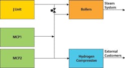
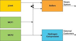
Previously, only the older J Unit provided hydrogen for external customers. Switching to cleaner mercury-free hydrogen produced by the MCP's advanced-membrane-cell electrolysis method enabled us to furnish higher-quality product — and use the J Unit's hydrogen to power our onsite boiler (Figure 1).
Because the MCP hadn't supplied hydrogen externally before, we had to design and implement a new control strategy to enable flexible use of compressors to service variable demand from external customers. The new strategy had to prevent extreme differential pressures — for example, from a compressor startup — that could cause the MCP to trip or damage its membranes.
Once again we set about designing, modeling and testing various control strategies until we found one that allowed linking the compression plant to the MCP without unacceptable disturbances. The dynamic simulation enabled us to accurately predict system performance before commissioning took place. This gave everyone confidence that investing in the compression project would pay off.
The control system now carefully monitors and regulates differential-pressure variations potentially affecting the compressor, burners and MCP membrane. An auto-isolation limit vents off hydrogen temporarily to prevent any damage to the membrane.
Previously, boilers received hydrogen from only a single production stream (either MCP1 or MCP2) at any one time because pressure variations between the two streams increased risk of a boiler trip. Because the new control strategy minimized these variations, we immediately could use a dual stream, which boosted the amount of hydrogen we could send to the boilers.
When a production electrolyzer in the MCP is offline, it's purged with nitrogen gas. The new system enables this nitrogen to be removed without disturbing hydrogen pressure — ensuring customers receive pure hydrogen and avoiding MCP trips.
Maintaining a Solid Foundation
The new control strategies depend upon both instrumentation and control valves working precisely; otherwise we wouldn't be able to reach optimum plant performance levels.
Maintaining this high level of instrument and valve performance has been simplified by the Rosemount pressure and flow devices and Fisher intelligent valves used throughout the compressor, boiler and chlorine plants. Like the control system, they are part of Emerson's PlantWeb digital plant architecture and communicate instrument health as well as process information using Foundation Fieldbus.
We use Emerson's AMS Suite predictive-maintenance software and AMS ValveLink software tool to gather health data, check that valves are working at their optimum levels, and ensure there's no stiction that could affect control performance.
Improving Step by Step
Design and installation took 18 months. While this might seem a long time, a cautious approach was essential to avoid any disruption to chlorine production. Commissioning occurred in August 2008.
We built confidence and acceptance within the production team by gradually introducing elements of the new control strategy, which allowed us to verify that performance fully matched modeled predictions. We did this in two major phases, each time increasing the amount of hydrogen that could be burned in the boilers.
We also implemented a new monitoring system to automatically calculate venting totals and costs based on actual gas prices. Since we started the project, the site has reduced hydrogen venting by 90%. The resulting increase in hydrogen available to fuel the boilers has saved us several million pounds/year in natural gas. In addition, the improved control has prevented many boiler trips and events that would have exposed MCP membranes to unfavorable pressures.
Not wanting to rest on our laurels, we already have designed further improvements to the MCP differential-control system that provide an instant response to load changes and better response to boiler starts and trips below the auto-isolation limit.
Philip Masding is process control manager for INEOS Chlor, Runcorn, U.K. E-mail him at [email protected].
INEOS Chlor is a sister company to INEOS NOVA, a CP 50 company.
