When the desired vacuum condition isn’t provided at a process plant, production often comes to a halt and all eyes become focused on the vacuum pump as the root cause of the problem. However, the vacuum pump usually isn’t culprit. In almost all cases, either: 1) the pump is being operated in a condition for which it never was intended, 2) one or more of the user’s interface points with the pump (suction/discharge lines, water supply, process contaminant, etc.) are being operated outside of design parameters, or 3) the vacuum chamber or vacuum lines were improperly specified. Each vacuum pumping technology will react differently to various conditions, so it’s not possible to offer a “one size fits all” answer to the problem. The following is a guide to systematically identifying the root cause of the most common problems and correcting them based on general vacuum system recommendations as well as technology-specific issues.
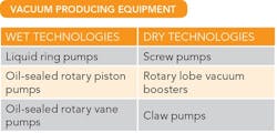
Let’s start by noting that vacuum technologies found at plants generally fall into two categories: wet and dry. The terms “wet” and “dry” refer to whether or not the user’s process gas comes into contact with a liquid as the gas passes through the vacuum pump. Wet technologies utilize a liquid to create a seal between the discharge and the suction of the pump to minimize the “slip” of gas backwards from the discharge to the suction and increase volumetric pumping efficiency. Dry technologies have no liquid contact with the process gas. Table 1 lists common vacuum equipment of both types.
Table 1. Common options rely on either wet or dry technologies.
General Recommendations
The following points apply to all vacuum systems regardless of pump type:
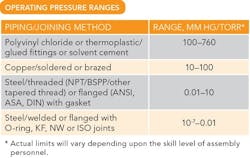
Vacuum leaks. All vacuum systems have some amount of air-in leakage, which may or may not be known at the time the vacuum pump is sized. Excessive system leaks result in reduced process gas pumping capacity because the pump must move not only the process gas from the vacuum chamber but also the air-in leakage. Leaks occur at the joints of the vacuum lines and at the vacuum chamber. To avoid excessive air-in leakage, bear in mind the general recommendations of operating pressure ranges for various piping materials and joining methods detailed in Table 2. Note that actual limits will depend upon the skill level of assembly personnel.
Vacuum pump or system problem? You must determine if the issue is caused by the pump or by other equipment in the vacuum system. To find out, mount an isolation valve and an accurate vacuum gauge in-line as near to the suction connection of the vacuum pump as possible. Close the isolation valve and then measure the ultimate vacuum (also called blank-off) performance of the pump. Compare the measured vacuum to the manufacturer’s published ultimate vacuum value. A value reasonably close to the published one indicates the issue stems from leaks or outgassing in the vacuum system.
Table 2. The level of vacuum necessary determines the construction options.
Excessive pump discharge or backpressure. A vacuum pump is designed to discharge to atmospheric pressure or just slightly above unless the manufacturer specifically designates it a compressor. As the discharge pressure of the pump increases above atmospheric pressure, this raises the differential pressure across the pump, resulting in:
• higher pump temperature and possible overheating, leading to pump seizure; and
• increased current draw and subsequent overheating of the electric motor or an overload/fuse/breaker fault.
Improperly sized suction and discharge lines. Sizing of system piping significantly affects pump performance and should be performed by qualified vacuum engineers. However, to avoid problems, apply the following guidelines:
• Suction and discharge lines never should be smaller than the suction or discharge connection size on the vacuum pump.
• For every 50 ft of suction or discharge piping, increase the pipe size by one nominal pipe diameter. Example: A vacuum pump has a 2-in. inlet connection. The suction line between the pump and the vacuum chamber is to be 70 ft long. To avoid restrictions to gas flow and pumping performance issues, increase the vacuum line to 3 in.
Isolation of pumps operated in parallel. Many vacuum pump installations consist of multiple pumps operating in parallel and utilizing a common suction and discharge header. For these type of installations, isolate idle pumps from those in operation at the suction and discharge. Failure to isolate the offline pumps may result in: 1) discharge gas from the operating pumps entering an idle pump and contaminating it, and 2) creation of vacuum in the idle pump and a resulting liquid back-stream into the vacuum lines and chamber.
Now, let’s look at specific issues that might affect particular equipment.
Liquid Ring Pumps
Several possible operating conditions can cause insufficient vacuum in liquid ring (LR) pumps. The most common are:
• too high sealant vapor pressure;
• incorrect sealant flow rate; and
• process contamination of the sealant (in full sealant recovery systems).
Too high sealant vapor pressure. A LR pump utilizes a sealant. Most commonly this is water but other liquids may be used based on the specific application of the pump. Generally, the lower the temperature of the sealant, the lower its vapor pressure, which results in increased pumping capacity and deep vacuum performance. In addition, as the process vacuum level approaches the sealant’s vapor pressure, the sealant will begin to flash from the liquid to the vapor phase (cavitation), subsequently displacing the pump’s capacity. Utilize sealant temperature/capacity correction factors from the specified LR pump manufacturer to properly size the pump.
As a rule of thumb, to avoid pump cavitation select a sealant whose vapor pressure, Pv, at operating temperature is less than half of the required vacuum level, P1, as measured at the pump inlet. For instance, the Pv of water at 60°F (15°C) is 13.3 mm Hg absolute. Therefore, the lowest vacuum operating pressure for the pump would be:
P1 = (2)(13.3) = 26.6 mm Hg
Operating the vacuum pump’s suction pressure below this level will result in cavitation of the water within the pump that ultimately can damage the pump’s impeller (Figure 1).
Figure 1. Operating at a suction pressure below the lowest recommended pressure can cause cavitation that damages the impeller.
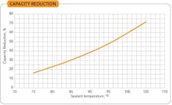
Water at too high a temperature supplied to the pump directly as sealant or indirectly as coolant to the heat exchanger of a full sealant recovery system will increase the sealant’s vapor pressure. As the vapor pressure increases, this value may approach the vacuum level of the pump and cause the sealant to flash and reduce the pumping capacity. In many cases, the use of cooling tower water in high ambient temperature climates (>95°F or 35°C) results in significant capacity reduction. Figure 2 illustrates the capacity reduction when operating a pump at 75 torr should water sealant become much hotter than the desired 60°F.
Incorrect sealant flow rate. Each model of a particular manufacturer’s LR pump has a specific sealant flow rate requirement to achieve the published vacuum performance. Regulate the sealant flow to within approximately ±5% of the published requirement. Simple and inexpensive flow control devices are available to regulate this flow.
If too much sealant is fed to the vacuum pump, the volume of the liquid ring within the pump will increase. This will reduce the volume of the rotor available for the pump to move process gas and the pump will lose pumping capacity, resulting in a loss of vacuum.
If too little sealant is fed to the vacuum pump, the liquid ring volume will decrease. The liquid ring no longer will be able to create the necessary seal between the rotor and the housing, allowing internal “slip” of the discharge gas back to suction and resulting in reduced pumping capacity and loss of vacuum.
Figure 2. Pump operating at 75 torr suffers significant capacity reduction when sealant water is markedly hotter than the desired 60°F.
Process contamination of the sealant (in full sealant recovery systems). Such contamination can involve carryover of condensate or particulates.
During the process of moving gases from the vacuum chamber through the LR pump, the process gas will contact the sealant and subsequently may collect in the sealant. If the substance collects in the sealant liquid and has a vapor pressure higher than that of the sealant, it will enter the LR pump and flash from the liquid to the vapor phase, reducing the pump’s capacity. As an example, when using oil as the LR sealant, if water vapor is a carryover product from the process gas, the vapor will condense to liquid in the discharge separator tank and effectively increase the pump sealant vapor pressure and decrease capacity.
Carryover of particulates or other solids may clog sealant piping, strainers, heat exchangers, valves, etc., and restrict sealant flow to the vacuum pump, resulting in reduced pumping capacity and possible overheating of the LR pump.
Oil-Sealed Rotary Pumps
Some of the most common field issues experienced by oil-sealed rotary piston pumps and rotary vane pumps are:
• belt squeal/high amp draw at startup;
• inability of pump to blank-off/milky oil;
• back-streaming of oil into suction lines or vacuum chamber; and
• excessive oil mist discharge.
Belt squeal/high amp draw at startup. Belt squeal of a pump at startup can stem from: 1) improper belt tensioning, 2) cold oil temperature due to low ambient temperature, or 3) improper shutdown procedure.
Typically, a loose belt causes belt squeal. Check for looseness by starting the pump and observing the deflection of the belt during rotation. Do not apply belt dressing to V-belts such as those used on Tuthill vacuum pumps. If the belt appears to have excessive deflection, refer to the manufacturer’s product manual for proper tensioning instructions.
The next likely cause of belt squeal/high amps is attempting to start the pump in low ambient temperature conditions, typically <60°F (15°C). In this case, you must install oil preheaters to increase the oil’s temperature and reduce its viscosity so the internal components don’t create high torque on the shaft. It often makes sense to use a temperature switch to ensure the pump will not start until the heaters have raised the oil temperature enough.
Lastly, oil-sealed rotary piston pumps are particularly prone to improper shutdown. A pump shut down under vacuum will leave an excessive amount of oil in the cylinder. Then, when an operator attempts to start the pump, the cold viscous oil will create high torque on the pump shaft, resulting in high amp draw. Oil-sealed pumps require that the inlet pressure of the pump be increased sufficiently (typically >100 torr for no less than 15 sec.) to allow more gas flow through the cylinder of the pump, resulting in displacement of the oil in the cylinder back into the main oil reservoir.
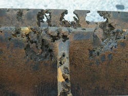
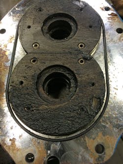
Figure 3. Accumulation of baked-on material can eliminate essential clearances and lead to pump failure.
Inability of pump to blank-off/“milky”oil. Oil-sealed vacuum pumps commonly fail to meet the published blank-off performance due to: 1) substitution of the manufacturer’s vacuum pump oil with an improper oil, or 2) condensable process vapors collecting in the oil.
Vacuum pump operators for various reasons may not use the manufacturer’s recommended oil. This often can result in failure to produce the deep vacuum results as published. Vacuum pump oils are formulated to have a vapor pressure significantly lower than the pump’s ultimate vacuum capability. If a higher vapor pressure oil is substituted, the pump will begin to create vacuum and reach the vapor pressure of the oil in the cylinder. When this occurs, the oil will flash to the vapor phase, displace the pump’s capacity and result in higher blank-off values. The only remedy is to use an oil that has a vapor pressure equal to or less than that of the manufacturer’s vacuum pump oil. Matching the recommended oil’s viscosity also is necessary.
Many processes such as vacuum drying contain moisture that will condense when it reaches the pump’s oil reservoir at atmospheric pressure. The visual result is “milky” oil. Typically, the liquid has a vapor pressure significantly higher than the pump’s ultimate pressure. As the condensed liquid is recirculated with the oil into the cylinder (under vacuum), it begins to flash to a vapor phase. This again results in a higher-than-published blank-off value. The solution is either to: 1) run the pump’s gas ballast valve open (off process) for 15–30 minutes, allowing the incoming air to strip the moisture from the oil, or 2) change the oil more frequently. Note that failure to perform one of these procedures will result in excessive wear of the internals due to increased friction and heat and, thus, reduced pump life.
Back-streaming of oil into suction lines or vacuum chamber. This commonly stems from failure to vent the pump’s inlet prior to shutdown. As already noted, oil-sealed pumps require that the inlet pressure of the pump be increased sufficiently (typically >100 torr for no less than 15 sec.) to allow more gas flow through the cylinder of the pump, resulting in displacement of the oil in the cylinder back into the main oil reservoir.
Excessive oil mist discharge. This phenomenon typically occurs because: 1) the pump has been operated continuously at an inlet pressure greater than the manufacturer’s recommendation, or 2) the pump’s oil mist element has failed.
Oil-sealed pumps commonly are used to operate continuously at inlet pressures <10 Torr or for short pump-down cycles that don’t allow oil to saturate the pump’s oil coalescing element. If a pump is operated above the manufacturer’s recommended maximum for prolonged periods, the relatively high gas density will carry the oil into the mist element at rates beyond its maximum filtering capability. The result is oil discharge from the exhaust of the pump. The best way to avoid this situation is appropriate sizing of the pump for the system design to avoid high operating inlet pressures for prolonged periods.
The other possibility is that the pump’s oil mist element fibers have separated due to continuous saturation and high pressure differential, resulting in the escape of oil mist from the pump’s exhaust. Replacing the element commonly will solve the problem.
Dry Screw Pumps
The two most common issues related to the improper application or operation of dry screw vacuum pumps are:
• overheating and pump seizure; and
• high motor amp draw.
Note that while dry screw vacuum pumps all have some common features, the symptoms of each pump will be manufacturer and model specific.
Overheating and pump seizure. Dry screw vacuum pumps are susceptible to several potential causes of overheating. The more common are:
reduced cooling water flow/high cooling water temperature; high inlet gas temperature; and improper staging with a vacuum booster.
The dry screw pump is more sensitive to cooling water flow and temperature than other technologies. A reduction in cooling water flow rate below the manufacturer’s minimum recommendation or supply cooling water temperatures in excess of the manufacturer’s recommendation can result in thermal growth and, ultimately, seizure of the pump.
Because dry screw pumps have no internal liquids to absorb heat, their internal temperatures can range from 250°F to 450°F depending upon the screw design. So, they are sensitive to inlet gas temperatures; each pump has a manufacturer’s maximum inlet gas temperature rating. Unfortunately, this value sometimes isn’t considered during the selection process and, as a result, the pump might encounter entering gas temperatures that exceed this value, resulting in excessively high internal gas temperatures that cause thermal growth and subsequent pump seizure.
The sizing process of a pump with a vacuum booster requires consideration of several parameters. One of the most important when pairing a vacuum booster upstream of a dry screw pump is staging ratio. This is defined as the ratio of the volumetric flow rate of the vacuum booster, V1, to the volumetric flow rate, V2: SR = V1/V2. Applying Boyle’s Law: V1/V2 = P2/P1.
Because V1 always is greater than V2, the pressure between the booster and the dry screw pump, P2, always will be greater than the inlet pressure, P1, to the system. The gas compression across the booster results in a temperature rise of the gas that will enter the dry screw pump. Therefore, carefully consider this ratio to avoid exceeding the inlet gas temperature rating of the dry screw pump.
High motor amp draw. Many types of rotating machinery experience high motor amp draw. Usually the cause isn’t an issue with the motor but rather with the piece of equipment it is driving. In the case of dry screw pumps, high amp draw typically results from: excessive discharge pressure (as noted in the general section); process buildup in the machine; or internal contact due to the cooling water and inlet gas temperature noted above.
Excessive discharge pressure as well as cooling water and inlet gas temperature already have been addressed, so, let’s focus on process buildup in the machine. Many vacuum processes contain chemicals that combine at high temperatures to form sticky or tacky materials that attach and then “bake onto” the screws (Figure 3). Their buildup ultimately creates a “zero clearance” condition inside the pump. This contact within the pump leads to additional torque on the pump shaft, resulting in increased amp draw.
Consult the pump’s manufacturer for a recommended solution. Generally this will involve either: 1) knocking out or filtering the process gases upstream, or 2) supplying a cleaning flush. Option 1 is preferable in extending pump life. However, filtration units can be costly and will require continual maintenance. In addition, as the filter elements clog, a resulting loss of vacuum in the process chamber will occur.
The cleaning flush option avoids the cost of the filtration system but may pose its own operational issues that could result in damage to the pump. Moreover, there’s no guarantee of success with the flushing process. Proper choice of flushing medium is most important and requires determining whether a solvent is needed to dissolve material or if a mechanical cleaning fluid such as water will suffice; the pump manufacturer should approve the selection. When injecting a direct liquid flush into a dry screw pump, take care not to flood the pump’s screw chamber as this can result in the pump attempting to compress liquid and subsequent mechanical failure requiring a major rebuild of the machine. Lastly, when injecting a flushing liquid into the pump’s process chamber, elevate the pump’s inlet pressure sufficiently above the vapor pressure of the liquid to avoid flashing. Such flashing to vapor will compromise cleaning as well as potentially create freezing problems within the machine due to the Joule-Thompson effect.
Achieve Long-Term Success
The process of creating a successful vacuum installation consists of several steps:
• Determine the parameters of the entire cycle of the vacuum operation from startup to shutdown.
• Select the appropriate vacuum technology and material of construction to match the process vacuum and flow requirement and gases to be handled.
• Properly size the vacuum pumping equipment, vacuum chamber and suction and discharge lines.
• Commission and leak check the vacuum system and validate on the process.
The vacuum pumping technologies addressed in this article are time-proven and will give years of reliable service when appropriately applied and operated. However, when troubleshooting is required, the pointers provided here should help you properly diagnose and address issues.
KEITH WEBB, P.E., is application engineering manager at Tuthill Vacuum & Blower Systems, Springfield, Mo. E-mail him at [email protected].

