Vacuum System Equipment: Make Sure You've Got a Good Flange Match
The plant was adding a three-stage steam-jet ejector vacuum system. We would talk occasionally with the local vendor representative to make sure that the order was on schedule. Everything had moved along as expected and the entire system of equipment would shortly be ready for export crating and shipment to the plant.
Shortly before the shipping date, the rep called to ask me out to lunch, which was very unusual for him. He obviously wanted something but I wasn't sure what. My boss told me to be less cynical and just enjoy a nice lunch. Lunch was nice and went well. Then the rep gradually approached me with a statement about a little problem with the vacuum system equipment. The purpose of lunch was finally out in the open.
The steam jet system had three stages with condensers after every stage. The condensers reduce the load to the next stage by condensing motive steam, any water vapor from the process, and process condensables. The first stage was designed with the ejectors directly attached to the first condensers. Three parallel trains were connected to a single seal drum (hot well).
We wanted at least one complete ejector assembly put together in the vendor shop before shipment. This required the ejector manufacturer to get the exchangers and do the assembly. The ejector vendor's preference was for each sub-supplier to ship components directly to our site. However, we pressed: Just humor us, assemble at least one in the shop. In the end, we reached an agreement to assemble a complete train.
The problem came in assembly. The 30-in. flange on the outlet of the first stage condenser didn't mate up with the 30-in. inlet flange of the condenser. Rush orders were being made to get matching flanges and repairs.
The episode took place well before the American Society of Mechanical Engineers (ASME) began official efforts in 1980 to develop a uniform flange design for lines with 26 in. and greater diameters. Until then, two different flange standards were common: those of the Manufacturer's Standardization Society (MSS) of the Valve and Fittings Industry, and of the American Petroleum Institute (API). The MSS-44 standard for Steel Pipe Line Flanges radically differed from the API-605 standard for Large-Diameter Carbon Steel Flanges.
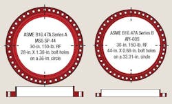
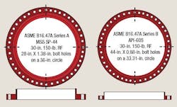
Figure 1. ASME standard includes both Series A and Series B flanges.
Figure 1 contrasts the size and bolt layout for Class 150 raised-face flanges. They obviously don't fit up. The ejector manufacturer had used one type of flange and its exchanger supplier had used another.
ASME sought a single unified design for nominal pipe size 26-in. to 48-in. flanges. Either MSS or API or both would have to change to create this standard. Neither would budge. So, today we have an ASME/ANSI standard that has two subsections. ASME B16.47 includes both a Series A equivalent to the MSS flanges and a Series B equivalent to the API flanges. For Class 150 and Class 300 (all sizes) and 36 in. and smaller in classes higher than Class 300, the Series A and Series B flanges aren't compatible.
So while our problem occurred before the ASME standard existed, having a single standard hasn't eliminated the issue. Occasional mismatches continue because of failure to correctly specify Series A or Series B. Few engineers appreciate that two potential flange types are available in large diameters. When you need a large-diameter flange, check what you have and make sure that's what you are going to get.
About the Author
Andrew Sloley, Plant InSites columnist
Contributing Editor
ANDREW SLOLEY is a Chemical Processing Contributing Editor.


