Tackle Tricky Kettle Reboiler Issues
To some, kettle reboilers have the reputation of having the most problems among all types of reboilers. I have not found that to be true. Outside of liquid entrainment in the reboiler vapor return line, few kettle-reboiler problems seem to come my way. Nevertheless, some do. This is the first in a series of three columns examining some of these more exotic kettle-reboiler failures.
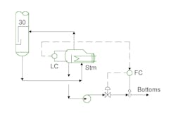
Figure 1 shows a schematic of a recent problem tower. Liquid from the bottom tray drops into the tower boot. An overflow weir in the reboiler lets excess liquid drop into a final level control area. This is not the only configuration for kettle-reboiler systems, but it is a common one. In this case, the reboiler elevation overlaps with the tower boot.
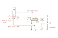
Hydraulic balance sets the liquid height in the boot. Liquid level in the boot varies in order to provide sufficient driving head for liquid flow to the kettle reboiler. Figure 2 illustrates the pressure balance. For simplicity, an elevation datum line has been defined as the elevation of the inlet nozzle to the kettle reboiler. The static head from the boot liquid level to the data line has to equal the static head from the datum elevation up to the weir in the exchanger plus the pressure drop losses in the system.
Htρt = ΔPliquid line + ΔPvapor line + Hwρw
Observed height in the tower boot, Hb, varies with the elevation difference between the nozzle levels of the tower and the kettle reboiler.
Sharp-eyed readers will note this is a simplified pressure balance. A more rigorous balance would include the effect of the height of liquid flowing over the baffle (weir) in the kettle reboiler and the effect of vapor density and elevation differences between the reboiler and the vapor return line location. While these effects do exist, they are so small in industrial applications that they are nearly always insignificant. The only time I’ve ever seen one of these become important was a side reboiler attached to a side draw on a column that had both a high vapor density and a very large elevation difference between the reboiler and the vapor return location.
The weir separates the boiling compartment of the kettle reboiler from the level control volume. In the case of the problem reboiler, the liquid leaving the kettle cascades to the bottoms flow control. This is a conventional approach for liquid inventory.
The reported plant symptom was too low a bottoms rate, causing pump ‘cavitation’ problems. The operators responded by reducing the duty of the reboiler with the intent to increase the bottoms rate. A higher bottoms rate would improve pump operation by avoiding cavitation. Even this short problem statement raises many questions.
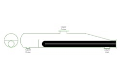
Skipping to the relevant one, let’s examine the operation of the overflow and the overflow liquid retained inside the reboiler shell. Figure 3 shows a scale side-view and end-view of the reboiler. Liquid enters the exchanger near the bundle head, vapor leaves from the top nozzle, and product liquid leaves from the nozzle downstream of the internal baffle. On first inspection, this looks like a conservatively designed exchanger. There is ample vapor-liquid disengaging volume above the exchanger bundle to prevent entrainment; distance between the bundle and the overflow weir allows for reasonable vapor degassing from the liquid, and the volume and size downstream of the weir appear ample. Calculations back up all these observations. Nevertheless, operators still have problems.
Some carefully controlled tests showed that now clear relationship between duty and pump problems. However, changing the setpoint of the level controller had significant changes. A higher liquid level made the pump problem go away completely. The level change was only slight, about six inches. This much of a level change should not significantly change pump NPSH available or pump performance.
Key Takeaways
- Kettle reboilers can experience issues with vapor entrainment in the reboiler vapor return line, which can lead to problems like pump cavitation.
- The liquid level in the kettle reboiler needs to be carefully balanced to prevent vapor entrainment — a slightly higher liquid level can resolve vapor entrainment issues.
- Tightly designed kettle reboilers are more susceptible to issues with changing operating conditions leading to vapor entrainment, so conservative design with ample liquid inventory and vapor disengaging volume is important.
The cause of the problem was vapor entrainment in the pump suction. Despite the large nominal size of the disengaging areas, some vapor bubbles were entrained into the pump suction. The vapor bubbles created a pocket in the feed line to the pump, dramatically increasing the pressure drop in the pump feed line. Having a higher liquid level in the kettle allowed for better disengagement and dramatically reduced vapor being pulled into the pump suction line.
Thermal imaging showed that the liquid level controller had a calibration problem. The actual liquid level at the control point was much lower than expected. Fixing the level controller completely fixed the operating problem.
While this exchanger had ample sizing, many exchangers are tightly designed to operating conditions. Vendors do this to keep bid costs down and get the purchase order. A tightly designed exchanger with changed operating conditions can easily lead to vapor entrainment into the outlet nozzle.
If you see a similar problem, compare the size of the liquid inventory and weir overflow to what you would consider a very conservative tray design for examining residence times and liquid velocities. If the operation looks tight, try modifying the liquid level to see if the problem gets worse or better.
In part two, we will look at another less common kettle reboiler problem, which shows up in reboilers or vaporizers with mixtures that have a wide boiling range.
About the Author
Andrew Sloley, Plant InSites columnist
Contributing Editor
ANDREW SLOLEY is a Chemical Processing Contributing Editor.


